Skylight lateral shaping die

A side shaping and skylight technology, applied in the direction of forming tools, manufacturing tools, metal processing equipment, etc., can solve the problems of increasing maintenance costs and product quality risks, high mold manufacturing costs, reducing production efficiency, etc., to eliminate the scrapped parts. and the risk of mold damage, the effect of reducing mold development costs and reducing maintenance costs

Active Publication Date: 2015-03-04
CHERY AUTOMOBILE CO LTD
View PDF7 Cites 6 Cited by
  • Summary
  • Abstract
  • Description
  • Claims
  • Application Information

AI Technical Summary

Problems solved by technology

Their principles are similar. When producing a roof with a skylight, some molds need to pass through the skylight. This means that if you want to produce a roof without a skylight, you need to remove the mold that passes through the skylight. It can be seen that The defects of the above-mentioned molds are: 1) manual operation is required to switch the structure, which increases the workload of personnel, reduces production efficiency, and causes the risk of scrapped parts and mold damage caused by personnel misoperation; 2) the switching structure is complicated, resulting in the cost of mold production High, the reliability of the structure is reduced, and the maintenance cost and the quality risk of the parts are increased

Method used


Image

  • Skylight lateral shaping die
  • Skylight lateral shaping die
  • Skylight lateral shaping die

Examples


Embodiment 1

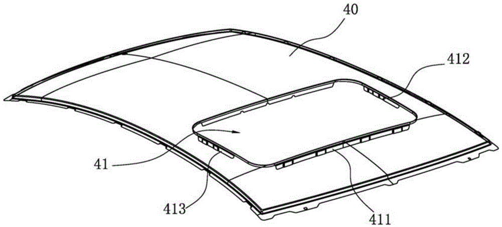
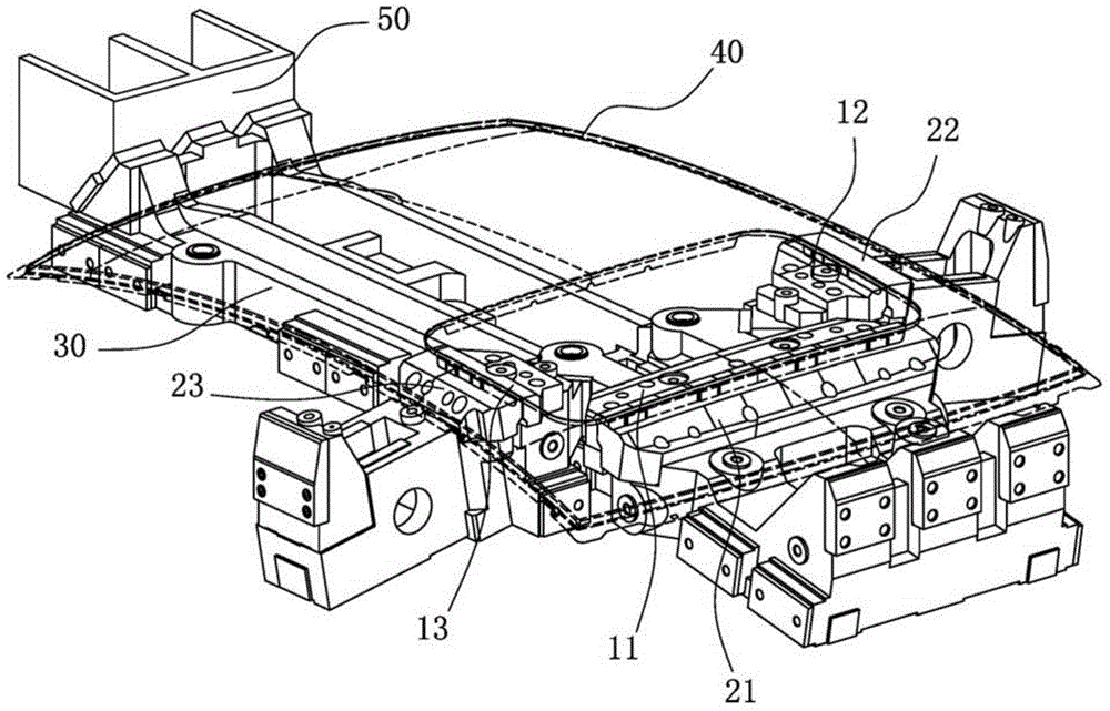
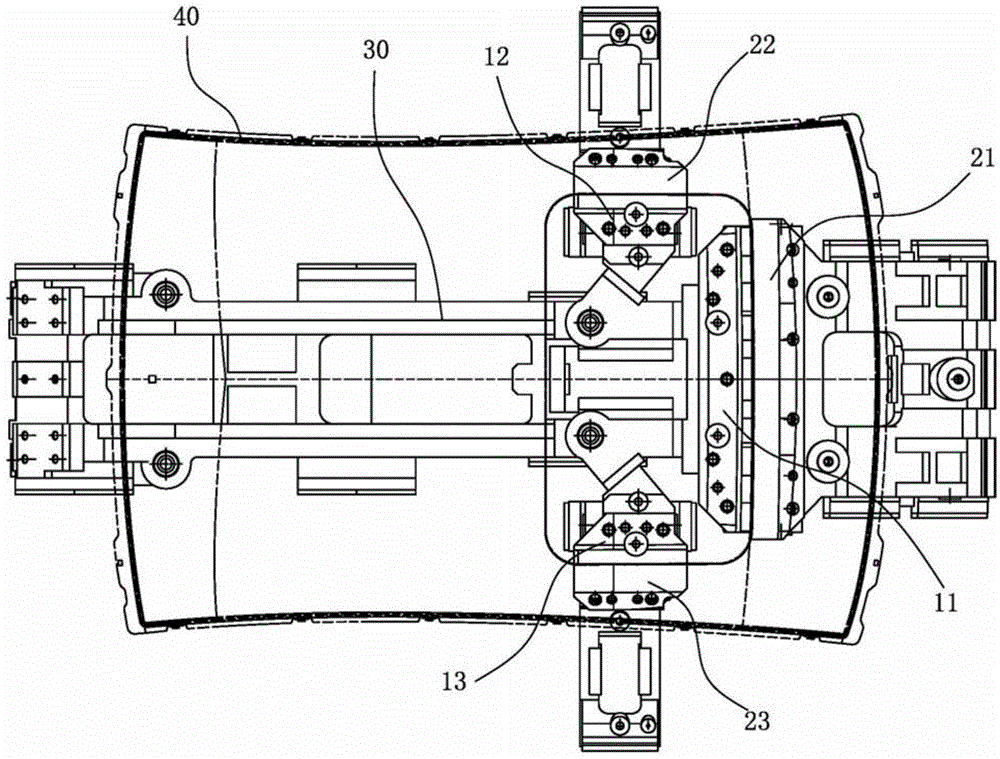
[0016] Such as image 3 , 4 As shown, as a preferred embodiment of the present invention, the first insert 11 is fixedly installed on the front end of the push rod 30, and the left and right sides of the push rod 30 are equipped with The oblique wedges 31 , 32 pressed against the flanges 412 , 413 on both sides of the skylight 41 constitute the transmission unit.

[0017] Further, the second and third inserts 12 and 13 are respectively provided with backing plates parallel to the slopes of the oblique wedges 31 and 32 , and the backing plates and the oblique wedges 31 and 32 form an inclined plane transmission fit.

Embodiment 2

[0019] Such as Figure 5 As shown, the first insert 11 is fixedly installed on the front end of the push rod 30, and a horizontally arranged connecting rod 33, 34 is respectively provided between the push rod 30 and the second and third inserts 12, 13, so that The connecting rods 33, 34 are hingedly connected to the push rod 30, the second and third inserts 12, 13, and the axes of the hinged shafts are arranged along the vertical direction.

[0020] As a preferred technical solution of the present invention, the lower mold base is also provided with elastic units for driving the first, second and third inserts 11, 12, 13 to reset, and the elastic units include corresponding The first, second and third inserts 11, 12 and 13 are provided with three compression springs or gas springs.

[0021] Further, the lower mold base is also provided with a limit block 14 for limiting the limit position of the push rod 30, the limit block 14 is located on both sides of the push rod 30, and ...


PUM


Abstract

The invention belongs to the field of automobile body sheet metal manufacturing, and particularly relates to a skylight lateral shaping die, which comprises a male die opposite to the inner side of the flange of a skylight, and a female die opposite to the outer side of the flange of the skylight, wherein the male die and the female die are respectively arranged on a lower die base slidably; an open-close type structure is formed between the male die and the female die; the male die and the female die are respectively driven by an inclined wedge driver block on an upper die base; the lower die base is also provided with a push rod for transmitting driving force of the inclined wedge driver block to the male die; the push rod extends to the outer side of the edge of a top cover through the lower part of the top cover from the skylight position; the push rod and the inclined wedge driver block form transmission fit on the outer side of the edge of the top cover. According to the skylight lateral shaping die, when the top cover without the skylight is produced, the skylight lateral shaping die can avoid the top cover, so that the skylight lateral shaping die has no need to be disassembled, the production efficiency is improved, and the risks of workpiece scrappage and die damage caused by misoperation are eliminated.

Description

technical field [0001] The invention belongs to the field of automobile body sheet metal manufacturing, and in particular relates to a sunroof side shaping die. Background technique [0002] The manufacture of the car top cover generally needs to go through four processes, namely drawing, trimming, front flanging, and shaping. for connecting other body parts. This shaping process is generally carried out for the edge flanging of the top cover and the edge flanging of the skylight. [0003] Most of the production lines of automobile OEMs have only four stamping machine tools, requiring parts to be completed in up to four processes. However, the skylights on the roof of most models have negative angles on all four sides, see figure 1 In the top cover 40 shown, three sides 411 , 412 , 413 of the skylight 41 are edged by molds, and the remaining edge is hemmed by a robot. Since the four sides of the skylight 41 have gone through three processes, i.e., drawing, trimming, and ...

Claims


Application Information

Patent Timeline
Patent Type & Authority Applications(China)
IPC IPC(8): B21D37/10B21D37/12
CPCB21D1/12B21D37/10B21D37/12
Inventor 宋体刚
Owner CHERY AUTOMOBILE CO LTD
Why Eureka
Try Eureka