Method for preparing porous material from short metal fibers

A technology of short metal fibers and porous materials, which is applied in the field of the preparation method of short metal fibers and its cutting device, can solve the problems of no mutual restraint of fibers, no guarantee of stability, difficulty in mass production, etc., and achieve small and uniform diameters, The effect of low production cost and no surface cracks

Active Publication Date: 2017-02-15
SOUTH CHINA UNIV OF TECH
View PDF6 Cites 1 Cited by
  • Summary
  • Abstract
  • Description
  • Claims
  • Application Information

AI Technical Summary

Problems solved by technology

This method can realize continuous production and processing of metal fibers with even fractures, but only fixed-length fibers can be processed. The fiber cutting is cut by the extrusion of a pair of cutters on the cutter head. The cutter head should not rotate too fast, otherwise the cutters will easily collide violently. Damage, at the same time there is no mutual restraint between the fibers, the fiber bundles may scatter, the stability of the operation is not guaranteed, and only one bundle of fibers can be processed, the efficiency is low, the cost is high, and it is difficult to mass produce

Method used


Image

  • Method for preparing porous material from short metal fibers
  • Method for preparing porous material from short metal fibers
  • Method for preparing porous material from short metal fibers

Examples


Embodiment 1

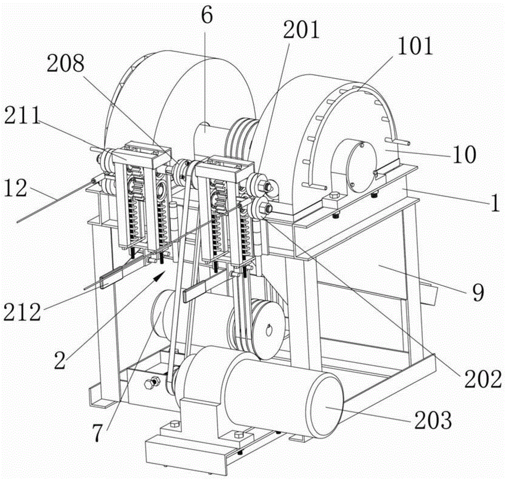
[0040] The preparation method of the short metal fiber of the present invention is firstly to make the long metal fiber wire material forward under the action of the pinch mechanism, and enter the through-die hole of the fixed knife die through the guide tube, wherein the The fixed knife die is equipped with a movable knife die that cooperates with it to cut the long metal fiber wire, and the outlet of the through die hole of the fixed knife die is a cutting edge; Continue to feed forward under the action, and pass through the through-die hole of the fixed knife die. When the long metal fiber material stretches out of the preset length through the die hole, the moving knife die makes a circular motion, and its linear blade The cutting edge of the die hole that is close to the fixed knife die passes, and the two blades form a pair of shearing motions, and finally cut the long metal fiber that protrudes through the die hole to produce short fibers of the required length.

[0041...

Embodiment 2

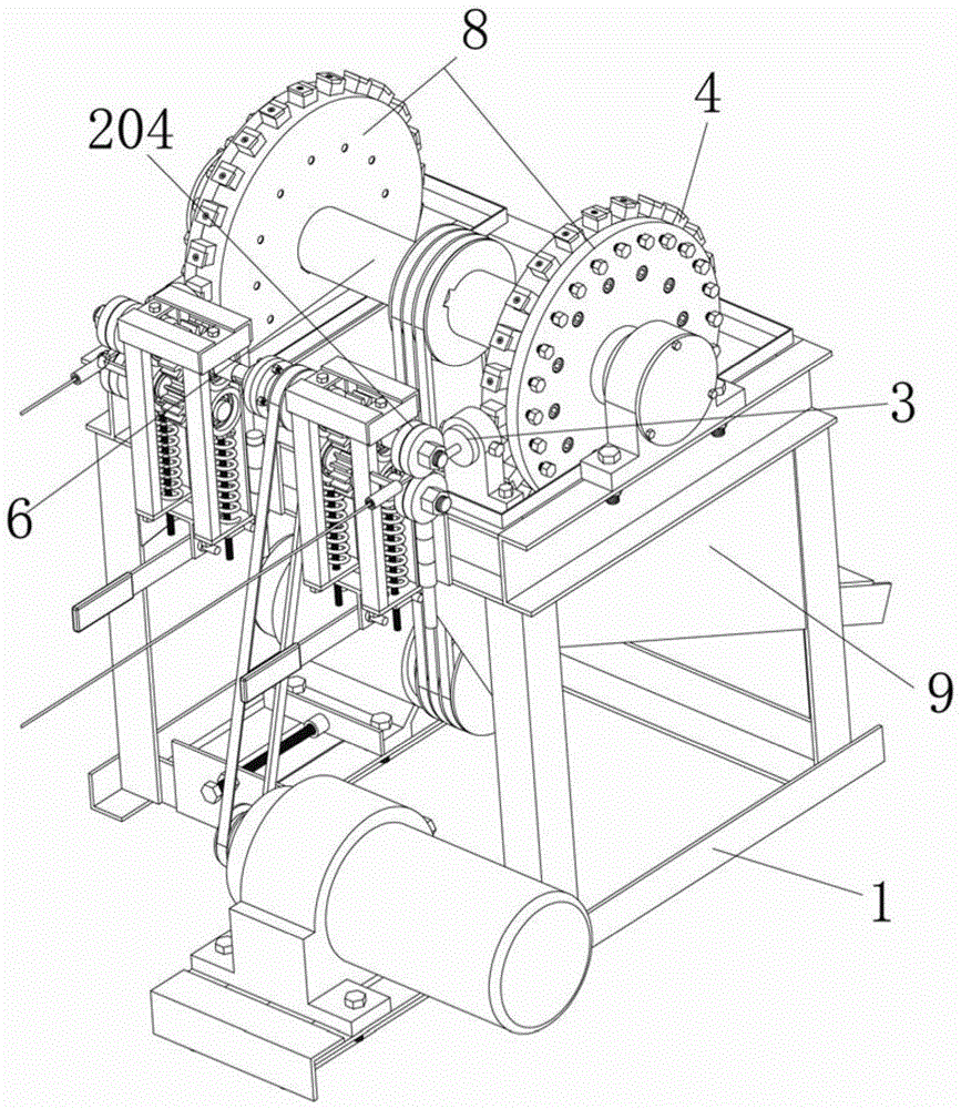
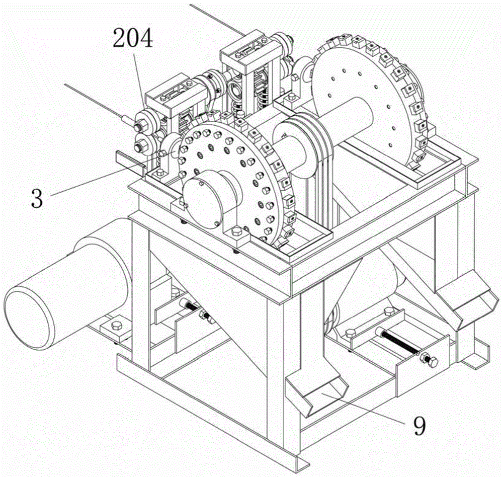
[0050] Such as Figure 9 to Figure 12 As shown, the difference from Embodiment 1 is that the pinch mechanism 2 described in this embodiment includes two relatively pressed and rotatable guide rollers 205, 206, and the guide rollers are driven to rotate by a power source. The roller surface is provided with a plurality of annular grooves 207 along its circumference at intervals along its length direction. The shape and size of the annular grooves 207 are adapted to the shape and size of the long fibers. The two guide rollers 205, 206 The annular grooves 207 on the top correspond one-to-one, and can be combined to form a plurality of passages for long fibers to pass through. One end of the long fiber 12 is placed in the corresponding passage, and the friction force of the guide roller realizes forward movement. send in. The rotating shaft 6 is equipped with at least two cutter heads 8 spaced apart, and in this embodiment there are eight specifically, and the periphery of each c...

Embodiment 3

[0052] Such as Figure 13 As shown, the difference from Embodiment 1 is that there are multiple fixed knife dies 3 (specifically twelve) arranged in the circumferential direction of the single cutter head 8 in this embodiment and the guide pressure guides matched with the fixed knife dies 3 . wheel set, such that the cutter head 8 rotates once a week, the twelve fixed knife dies 3 are sheared at the same time, and its efficiency is 12 times that only one fixed knife die 3 is arranged in the circumferential direction of a single cutter head 8 . As long as it is not limited by the spatial arrangement, the number of fixed knives arranged in the circumferential direction of a single cutter head 8 is not limited to twelve. In order to ensure that the shortened fibers can smoothly enter the collection chamber, the present embodiment Figure 13 The normal direction is perpendicular to the ground, that is, the rotating shaft 6 used to bring the cutter head 8 to rotate is perpendicula...


PUM


Abstract

The invention discloses a preparation method of metal short fibers and a chopping device thereof. The method comprises the following steps: firstly, metal long fiber materials are forwards fed under the effect of a clamping mechanism, are fed into a through mold hole of a fixed knife mold by a guide pipe, wherein the fixed knife mold is provided with a movable knife mold fitting the fixed knife mold to cut off the metal long fiber materials, and an outlet of the through mold hole of the fixed knife mold is a cutting edge; then, the metal long fiber materials are continuously fed forwards under the effect of the clamping mechanism, and penetrate through the through mold hole of the fixed knife mold; when the metal long fiber materials extend beyond a preset length of the through mold hole, the movable knife mold moves peripherally, and a linear edge thereof goes through next to the cutting edge of the through mold hole of the fixed knife mold; and the two edges form an opposite cutting movement to finally cut off the metal long fiber materials extending outside the through mold hole so as to obtain short fibers with the needed lengths. The method has the advantages of simple process steps, convenience for operation, easy execution and lower production cost, and is suitable for large-batch industrial production.

Description

technical field [0001] The invention relates to the technical field of preparation of short metal fibers and porous materials, in particular to a method for preparing short metal fibers and a chopping device thereof. Background technique [0002] As is well known in the industry, metal fibers are widely used in fiber composite reinforcement, conductive plastics, sound-absorbing , heat transfer and energy saving, battery electrodes, textiles, preparation of gas-permeable metal porous materials, lubrication and sealing, filtering exhaust, shielding sound absorption, microwave absorption and other fields. [0003] At present, the metal fiber preparation technologies mainly include metal melting high-temperature injection method (melt spinning method), drawing method, cutting method, and thermal decomposition method. The metal melting high-temperature injection method is a method of directly producing metal fibers from liquid metal. This method requires more complicated process...

Claims


Application Information

Patent Timeline
Patent Type & Authority Patents(China)
IPC IPC(8): B21F11/00B21F23/00
CPCB21F11/00B21F23/00
Inventor 周照耀杨德志吴菲
Owner SOUTH CHINA UNIV OF TECH
Why Eureka
Try Eureka