Compact plane branch coupler for single-pass or double-pass band

A branch coupler, compact technology, applied in the direction of waveguide devices, electrical components, connecting devices, etc., can solve the problems of resonance frequency shift, inflexible adjustment, etc., to achieve increased bandwidth, simple and flexible design, and good isolation Effect

Active Publication Date: 2015-03-04
XIDIAN UNIV
View PDF2 Cites 11 Cited by
  • Summary
  • Abstract
  • Description
  • Claims
  • Application Information

AI Technical Summary

Problems solved by technology

[0010] The purpose of the embodiment of the present invention is to provide a compact planar branch coupler applied to single or double passband, change the traditional microstrip line structure of the main line and the auxiliary line, and solve the existing miniaturization technology while realizing miniaturization The introduction of lumped components or the use of SIR structures will cause problems such as shifting of the resonant frequency or inflexible adjustment. At the same time, the size of the impedance can be adjusted arbitrarily to achieve different frequency ratios of the dual passband.

Method used


Image

  • Compact plane branch coupler for single-pass or double-pass band
  • Compact plane branch coupler for single-pass or double-pass band
  • Compact plane branch coupler for single-pass or double-pass band

Examples


Embodiment 1

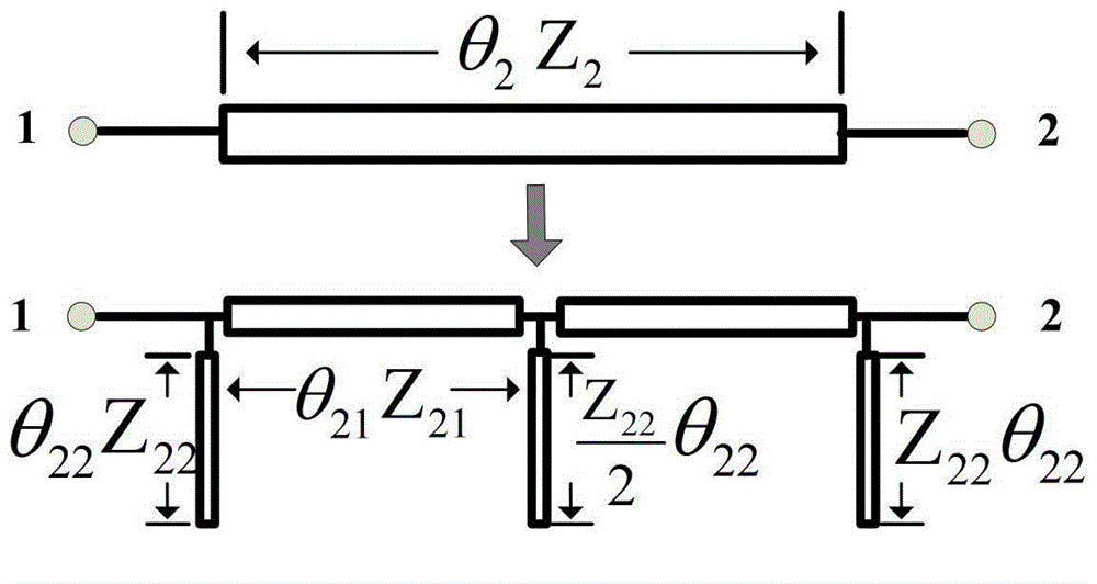
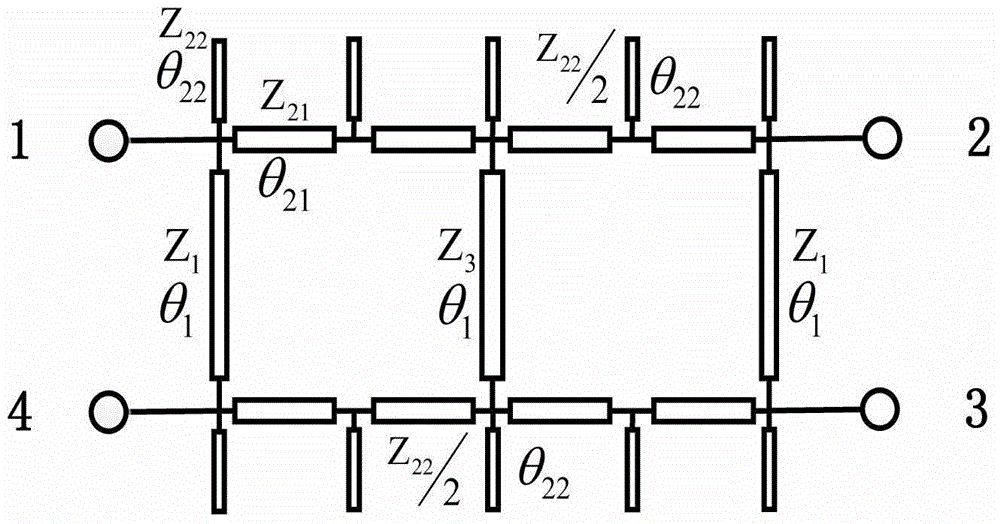
[0046] Such as figure 1 As shown, the main line of the present invention is cascaded two quarter-wavelength transmission lines, and each quarter-wavelength transmission line can be equivalent to the equivalent structure of two microstrip lines loaded with three open circuit stubs, the main line, The origin of the derivation of the equivalent circuit of the secondary line, the specific equivalent process is as follows:

[0047] The A-parameter matrix for a quarter-wavelength transmission line is: A 1 B 1 C 1 D 1 = 0 j ...

Embodiment 2

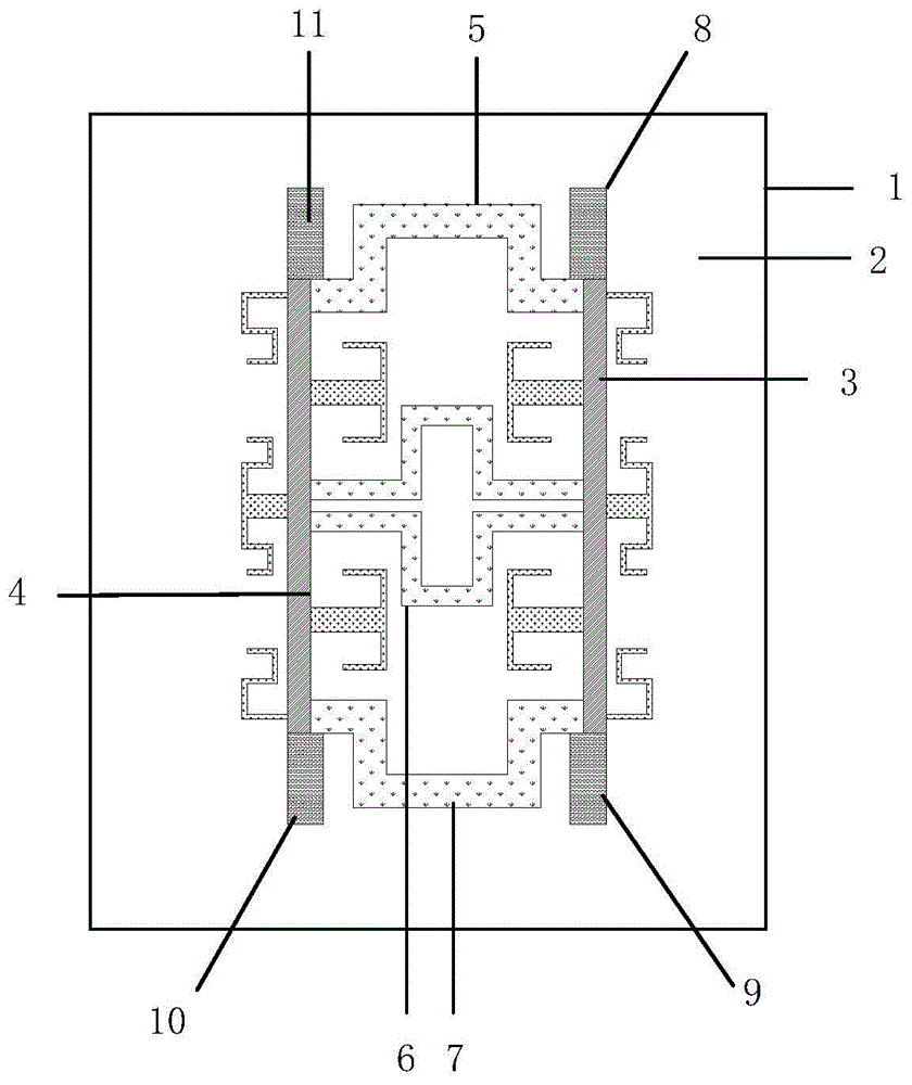
[0060] Based on the same inventive concept, the present invention also provides a dual-pass band branch coupler, such as Figure 6 As shown; Embodiment 2 of the present invention is also a branch coupler with a planar structure, mainly composed of: metal floor 1, dielectric substrate 2, main line 3, secondary line 4, first branch line 5, second branch line 6, third branch line A branch line 7, an input terminal 8, a first isolation port 9, a coupling terminal 10, and a second isolation port 11;

[0061] The metal floor 1 is arranged on the bottom surface of the dielectric substrate 2, the two ends of the main line 3 of the branch coupler are respectively provided with an input terminal 8 and a first isolation port 9, and the two ends of the secondary line 4 are respectively provided with a second isolation port 11 and a coupling terminal 10; Both the main line 3 and the auxiliary line 4 are composed of microstrip lines loaded with open stubs; the first branch line 5, the secon...


PUM


Abstract

The invention discloses a compact plane branch coupler for a single-pass or double-pass band, and the compact plane branch coupler is provided with a main line and a secondary line both which are symmetrical about left and right sides, and a branch line which is symmetrical about upper and lower parts, both ends of the main line are respectively provided with an input end and a first isolation port, both ends of the secondary line are respectively provided with a second isolation port and a coupling port, and the branch line is arranged between the main line and the secondary line and connected with them. The compact plane branch coupler adopts a micro-strip structure and has the advantages of compact design, simple processing, low cost and easy integration; to the coupler based on the branch line structure, the main line and the secondary line adopt the equivalent structure of the uploaded open-circuit branch knot, convenient to be miniaturized; the bandwidth is increased by the cascade structures of two quarter-wavelength branch couplers; the coupler has better isolation more than 20dB; according to the actual demand, the coupler can be adaptively improved, and the electrical length of the branch line is adjusted to twice of that of the single-pass band coupler branch line such that the coupler can be operated in the double-pass band environment.

Description

technical field [0001] The invention belongs to the technical field of high-performance microwave couplers, in particular to a compact planar branch coupler applied to single or double passbands. Background technique [0002] With the increasing development of wireless communication, various modern communication systems develop rapidly. In order to meet the requirements of modern communication systems, small size, wideband, and multi-passband passive devices have become the focus of research. In radio frequency systems, couplers can be used as power splitters, mixers, power combiners and phase shifters. They are widely embedded in electronic systems and become an important part of many microwave circuits. [0003] According to research reports, there are many types of couplers in terms of structure, with great differences, including: coaxial line type, waveguide type, microstrip line type and strip line type. From the perspective of the coupling mechanism, it is mainly div...

Claims


Application Information

Patent Timeline
Patent Type & Authority Applications(China)
IPC IPC(8): H01P5/18
Inventor 吴秋逸林明忠赵小敏史小卫黄丘林魏峰
Owner XIDIAN UNIV
Why Eureka
Try Eureka