
Cable hanging joint

A cable and cable clamp technology, applied in the field of cable suspension fixing devices, can solve the problems of inconvenient position adjustment, reduced conductive effect, increased resistance, etc., and achieve the effects of saving manpower and material resources, convenient two-way adjustment, and reducing workload

Inactive Publication Date: 2015-03-04
SUZHOU TIANYE MECHANICAL IND
View PDF6 Cites 0 Cited by
  • Summary
  • Abstract
  • Description
  • Claims
  • Application Information

AI Technical Summary

Problems solved by technology

After the cable is suspended on the suspension frame, the position of the cable is generally fine-tuned by pulling. During the pulling process, the friction between the cable and the suspension frame causes surface wear, especially the junction of the two cables is more likely to be damaged. Abnormal conduction accidents due to friction, such as poor contact between cables, reduced conduction effect, increased resistance, etc.
When a cable fails, it is necessary to check the cables in each suspension. Due to the large number of suspensions and the need to loosen the suspension for inspection, the troubleshooting workload is large, time-consuming and laborious.
The existing cable suspension frame also has the disadvantage of inconvenient position adjustment after installing the cable

Method used


Image

  • Cable hanging joint
  • Cable hanging joint

Examples


Embodiment Construction

[0015] The specific implementation manner of the present invention will be described below in conjunction with the accompanying drawings.

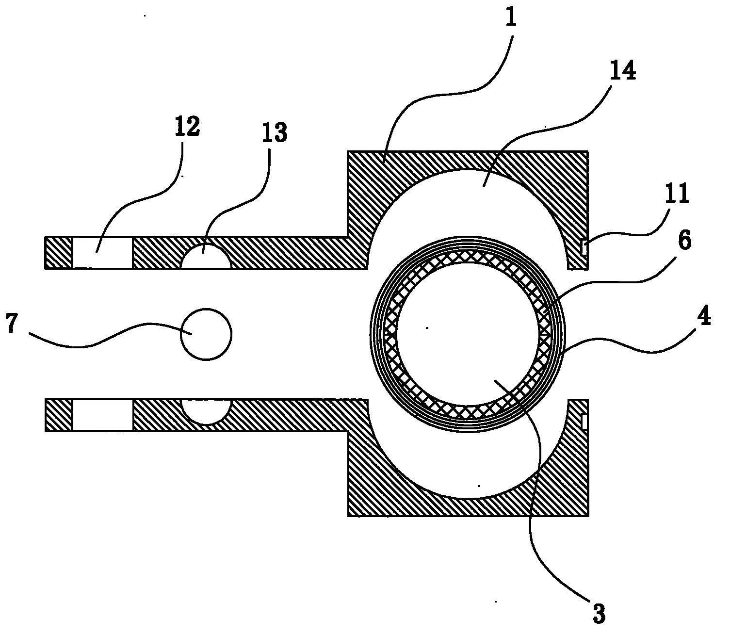
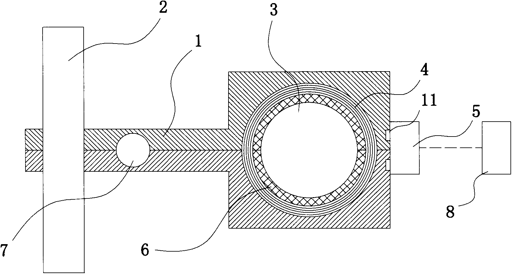
[0016] Such as figure 1 and figure 2 As shown, the cable suspension joint of this embodiment includes a joint body 1 formed by covering the upper and lower halves of the structure, and the joint body 1 has a cable clamping part and a mounting part;

[0017] There is a longitudinal cable clamping hole 14 in the cable clamping part, and a shielding ring 6 sleeved on the outer wall of the cable 3 is installed in the cable clamping hole 14, and the outer wall of the shielding ring 6 is wound and sleeved with a Hall coil 4;

[0018] The installation part has a longitudinal installation hole 13 and a vertical installation hole 12, the longitudinal installation hole 13 is installed on the vertical rod 7, and the vertical installation hole 12 is installed on the vertical rod 2; the joint body 1 is connected to the vertical rod 2 through the vert...


PUM


Abstract

The invention relates to a cable hanging joint. The joint comprises a joint body formed by enabling upper and lower two structures to be covered. The joint body is provided with a cable clamping partition and an installation portion. The cable clamping partition is provided with a longitudinal cable clamping hole; the cable clamping hole is equipped with a shielding ring sleeved on the outer wall of a cable; and the outer wall of the shielding ring is wound with a Hall coil. The installation portion is provided with a longitudinal installation hole and a vertical installation hole, wherein the longitudinal installation hole is arranged on a longitudinal rod; and the vertical installation hole is arranged on a vertical rod. The connection place, where the upper and lower two structures are covered, of the joint is equipped with a Hall sensor, wherein the Hall sensor is electrically connected with a signal collector. Longitudinal and vertical places of the joint can be adjusted through the longitudinal installation hole and the vertical installation hole, so that two-way adjustment of cable place and joint place can be carried out conveniently, and the operation is easy; and the current signal at the joint can be detected by the Hall sensor without detaching the joint, so that troubleshooting speed is fast, and workload is greatly reduced.

Description

technical field [0001] The invention relates to the technical field of cables, in particular to a fixing device for cable suspension. Background technique [0002] Power cables are generally buried underground or suspended on walls, and cables suspended on walls usually need to be sealed. The suspension of the cable is realized by the suspension frame. The suspension frame includes upper and lower clamping blocks engaged with the cable, and a shielding ring is sleeved at the contact between the clamping block and the cable. After the cable is suspended on the suspension frame, the position of the cable is generally fine-tuned by pulling. During the pulling process, the friction between the cable and the suspension frame causes surface wear, especially the junction of the two cables is more likely to be damaged. Abnormal conduction accidents due to friction, such as poor contact between cables, reduced conduction effect, increased resistance, etc. When a cable fails, it is ...

Claims


Application Information

Patent Timeline
Patent Type & Authority Applications(China)
IPC IPC(8): H02G3/06
Inventor 蒋云泉
Owner SUZHOU TIANYE MECHANICAL IND
Learn More