Electronic control module for mower

a technology of electronic control module and mower, which is applied in the direction of picking devices, agricultural tools and machines, and agricultural noise reduction, etc., can solve the problems of inefficient grounding and substantial electrical noise, inconvenient installation, and inconvenient maintenance, so as to reduce the cost of switches, reduce electrical noise, and save resources

Inactive Publication Date: 2006-02-02
BRANDON DENNIS +1
View PDF6 Cites 30 Cited by
  • Summary
  • Abstract
  • Description
  • Claims
  • Application Information

AI Technical Summary

Benefits of technology

[0007] In one exemplary form, the present invention improves upon the above-described systems by providing an efficient, inexpensive means of monitoring and controlling a wide range of mower conditions and functions. The present invention uses low voltage, thus reducing the cost of switches, wires and other components used, ensuring proper grounding, and reducing electrical noise. The electronic control module is programmed so that operation of the mower complies with applicable safety regulations, and can be modified to meet future changes in regulations. A display module, which can be a separate unit or integrated with the central control module, displays detailed diagnostic information to help the consumer operate the mower, which can reduce the number of inquiries from consumers as well as provide for easier troubleshooting by service technicians. In addition, a language key module can be added to allow the information to be displayed in different languages, thus increasing potential markets for the mowers.

Problems solved by technology

Moreover, such systems provide little or no guidance to the operator regarding what steps or actions to take to correct such conditions or problems.
In addition to limited feedback, current systems in use require high voltage running through the chassis of the mower, which results in inefficient grounding and a substantial amount of electrical noise.
The high voltage used also requires larger size, more expensive components.
Such systems also have limited functionality in monitoring and controlling mower operating systems, and do not adapt easily to changes in safety regulations.

Method used


Image

  • Electronic control module for mower
  • Electronic control module for mower
  • Electronic control module for mower

Examples


Embodiment Construction

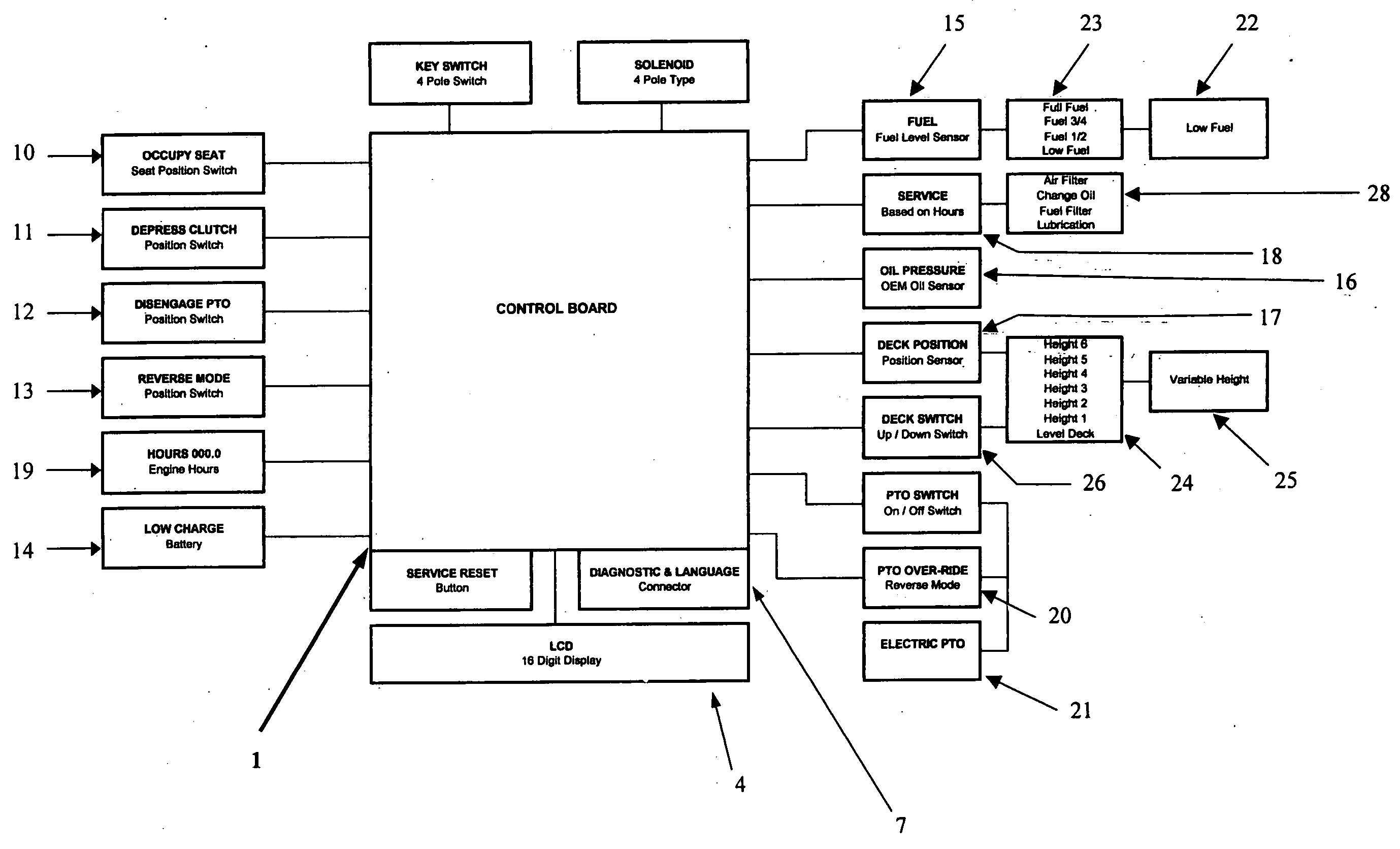
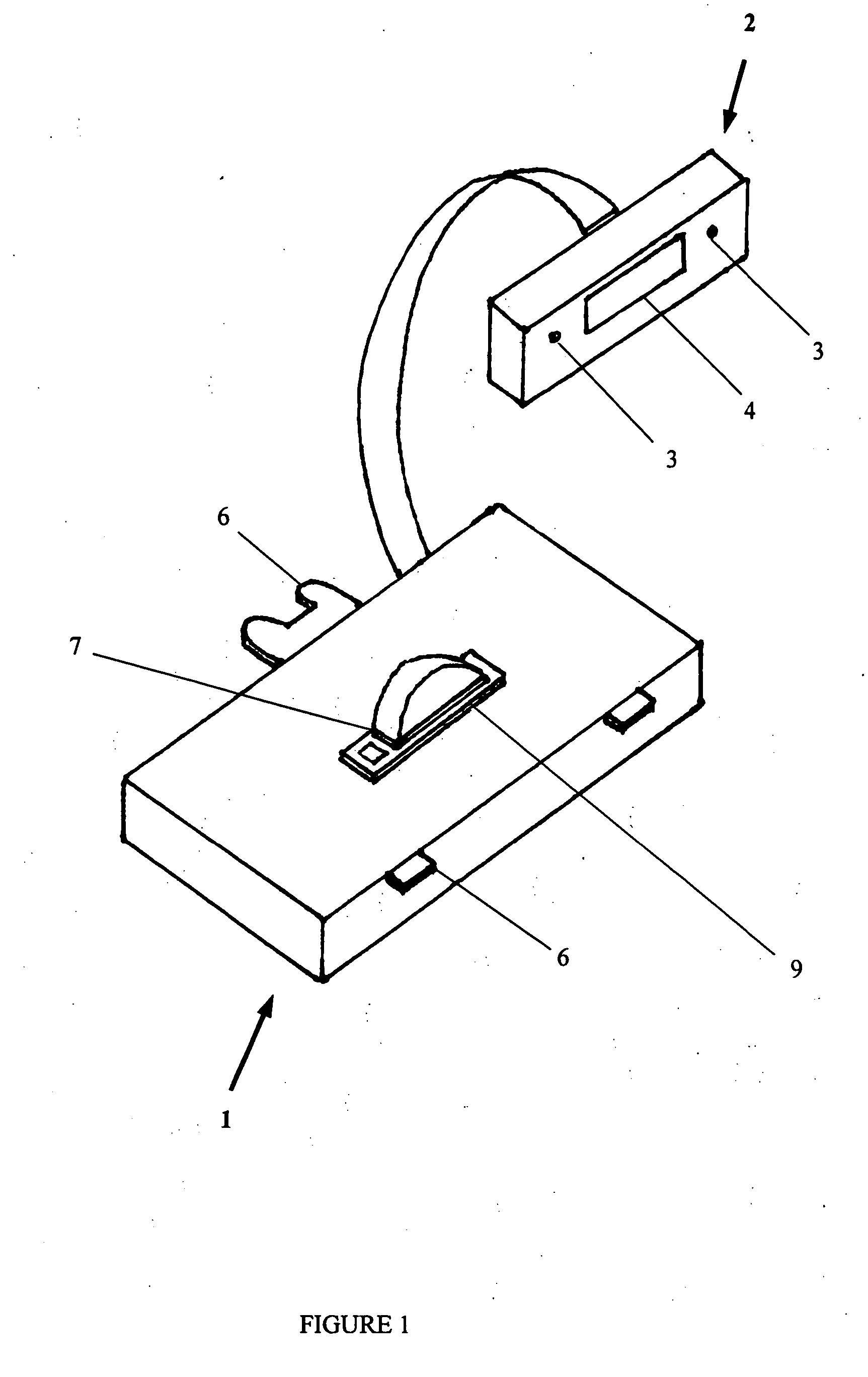
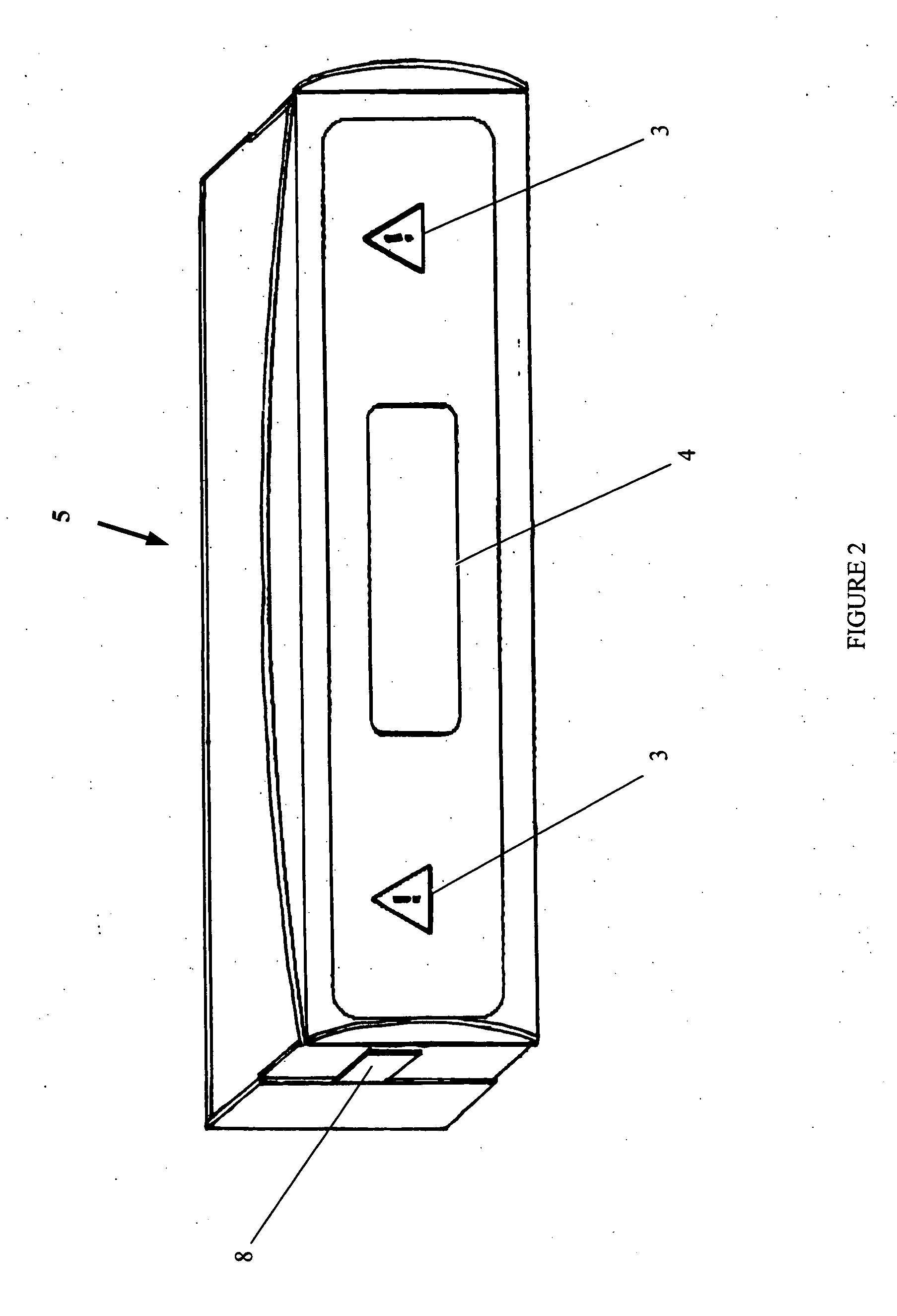
[0013] One exemplary embodiment, as seen in FIG. 1, shows the general configuration of a central control module 1 electrically connected to a separate display module 2. Alternatively, as shown in FIGS. 2 and 3, the display module 2 can be integrated with the central control module 1 into a single unit 5. The display module 2 can provide basic information about certain mower functions through LEDs 3, or more detailed alphanumeric information though a liquid crystal display (“LCD”) 4. In an alternative embodiment, the display module 2 may use both LEDs 3 and a LCD 4 to display information.

[0014] In one embodiment as shown in FIG. 1, one or more tabs 6 extend from the edges of the central control module 1. These tabs 6 may vary in size and placement, and are designed to allow the central control module 1 to be fastened into a appropriate slot or cutout on the mower (not shown) by a sideways sliding motion. The central control module 1 may thus be mounted in place without tools or sepa...


PUM


Abstract

An electronic control module to monitor and control various functions and conditions of a mower, and to display information about such functions and conditions to the operator of the mower. Information is accepted from a variety of switches and sensors on the various components of the mower, and information about certain mower functions can be displayed by means of LEDs or a LCD on a display module, which may be integrated with the central control module.

Description

FIELD OF INVENTION [0001] This invention relates generally to an electronic control module to monitor and control various functions and conditions of a mower, and to display information about such functions and conditions to the operator of the mower. BACKGROUND OF THE INVENTION [0002] The operation of lawn mowers, particularly riding lawn mowers, has been increasingly complex. The scope of functions to be monitored and conditions to be checked prior to and during mower operations has grown with improvements in mower technology and changes in safety regulations. Current devices monitor some functions and provide limited feedback to the operator in the form of light-emitting diodes (“LEDs”) that glow as warning indicators when certain conditions are met. Such devices, for example, cause a LED to be lit when the fuel is running low, the engine needs servicing, the battery charge is low, or the oil pressure is low. Other devices may include an amperage gage or hours-of-operation meter....

Claims


Application Information

Patent Timeline
Patent Type & Authority Applications(United States)
IPC IPC(8): A01D41/127
CPCA01D34/006A01D75/20A01D75/18
Inventor BRANDON, DENNISDAYTON, JAMES
Owner BRANDON DENNIS
Why Eureka
Try Eureka