

Metal-cutting machine tool for automatically machining steel reinforcement connection sleeve
A steel connecting sleeve and automatic processing technology, which is applied in the direction of metal processing machinery parts, metal processing, metal processing equipment, etc., can solve the problems of many processes, high labor intensity of workers, low efficiency, etc., and achieve the effect of improving thread accuracy
- Summary
- Abstract
- Description
- Claims
- Application Information
AI Technical Summary
Problems solved by technology
Method used
Image

Examples
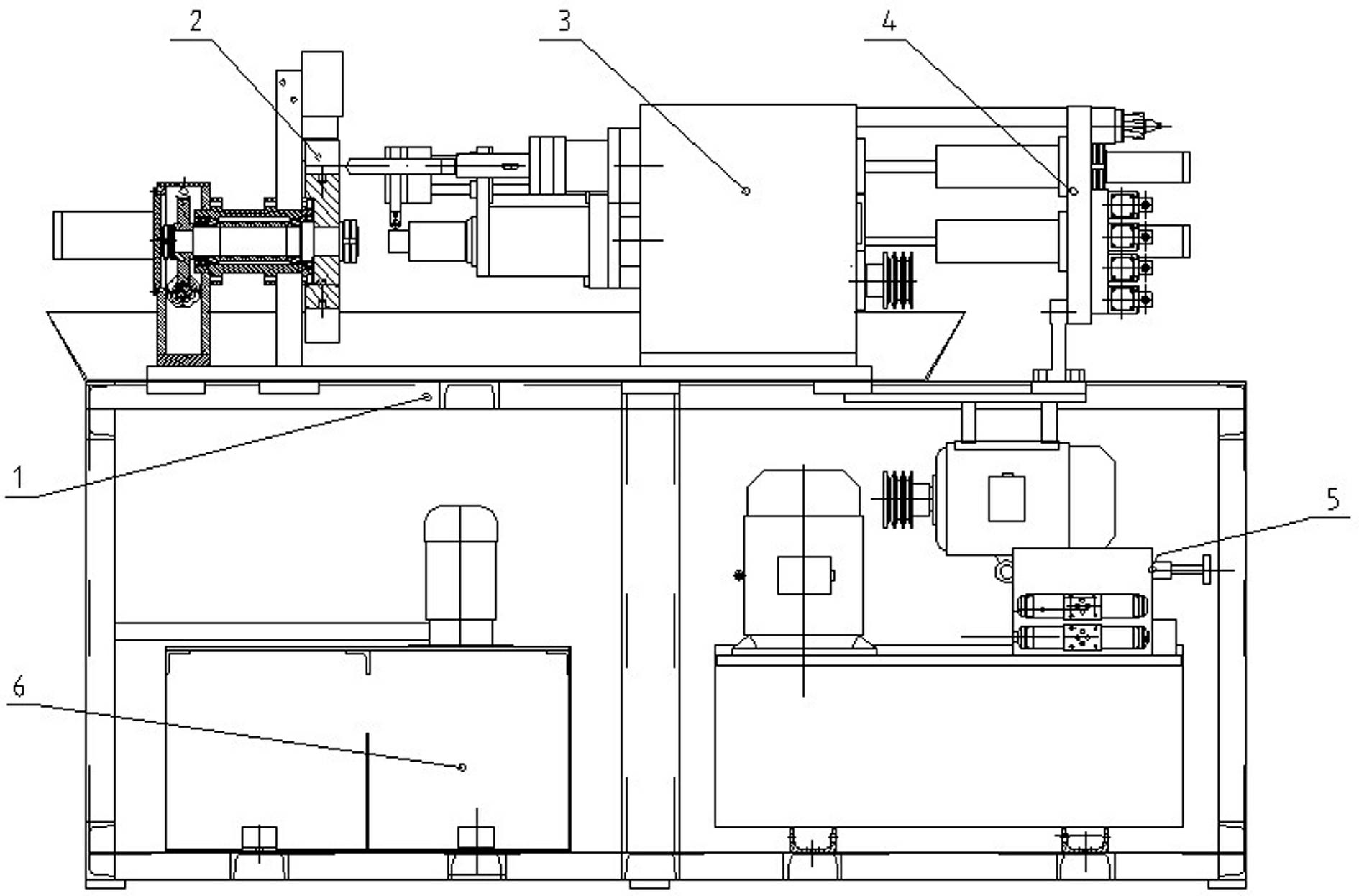
Embodiment 1
[0050] Example 1: Metal cutting machine tools for automatic processing of steel bar connection sleeves such as figure 1 As shown: its rotary table 2, spindle box 3 and hydraulic table 4 are arranged in a straight line and assembled on the upper part of the frame 1, and the hydraulic station 5 and cooling station 6 are installed on the lower part of the frame 1.
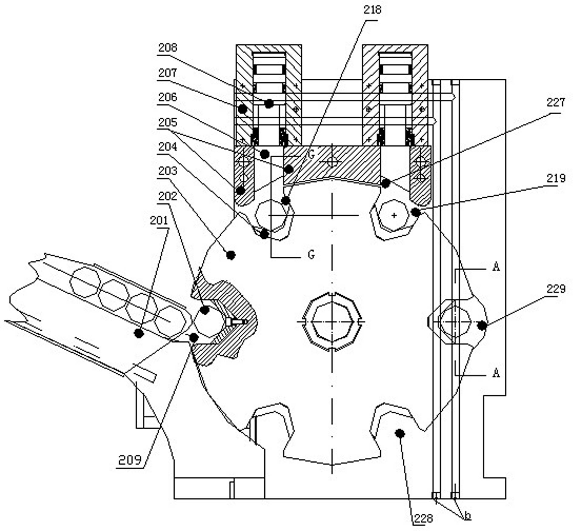
Embodiment 2
[0051] Example 2: Rotary table such as Figure 2-6 As shown: the bearing sleeve 216 is installed on the output shaft side of the worm gear box 211, and the other end of the bearing sleeve 216 is fixedly installed in the sleeve hole 230 of the wallboard 220, and the bottom surface of the worm gear box 211 and the wallboard 220 rely on The bearing sleeves 216 are connected into one body to form the stand of the rotary table 2; two 1# tapered bearings 215 are respectively installed at both ends of the bearing sleeve 216, and the rotary shaft 214 installed in the two 1# tapered bearings 215 One end fastens the worm wheel 212 and the encoder 210, and the other end of the rotary shaft 214 is fastened to install the disk-shaped rotary disk 203, which is located on the outside of the wallboard 220; the worm screw 234 is supported by a pair of 2# garden cone thrust bearings Supported in the worm gear box 211, the stepper motor 231 installed on the left end cover 232 of the worm gear bo...
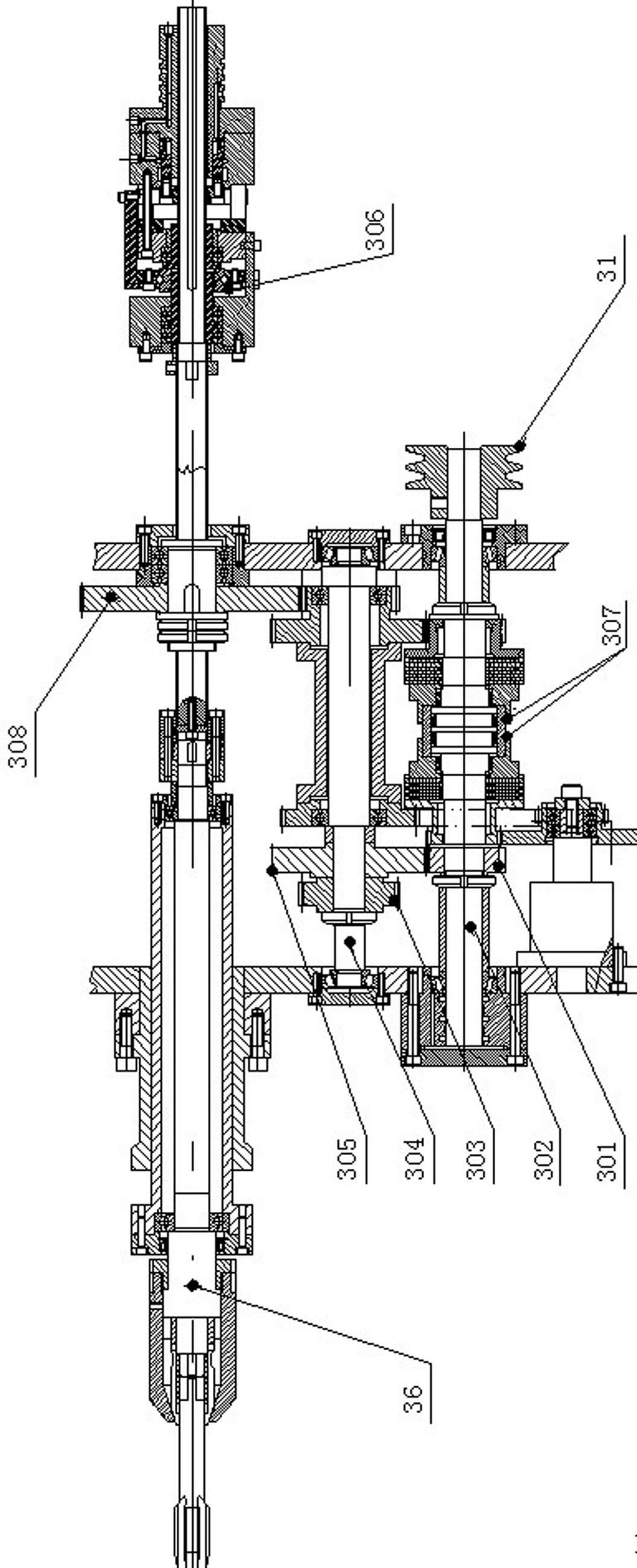
Embodiment 3
[0054] Example 3 : Integrated pressing cylinder and jacking cylinder such as Figure 2-7 shown ; Two pressing oil cylinders 207 and jacking oil cylinders 238 and their oil passages are integrally installed on the wallboard 220, the guide block 205 above the top surface of the disc-shaped rotary plate 203 and the two pressing blocks connected as one with the guide block 205 The oil cylinder 207 is fixed on the wallboard 220, and the inside of the guide block 205 is provided with two vertical rectangular hollow guide rails 227, and the square-section pressing block 206 slidingly matched with the rectangular hollow guide rails 227 can slide therein; the two pressing oil cylinders 207 respectively Align one by one with the square-section pressure block 206 in the vertical rectangular hollow guide rail 227, and the pistons 208 of the two compression cylinders 207 withstand the corresponding square-section pressure blocks 206 respectively; The 1# oil passage a connected with 207,...
PUM
 Abstract
Description
Claims
Application Information