A motor mounting bracket

A technology for mounting brackets and motor support, applied in the direction of electromechanical devices, casings/covers/supports, electrical components, etc., can solve the problems of adhesion, affecting the operation of the motor, and poor reliability, and achieves lower operating costs and stable installation. Reliable, Convenience-enhancing Effects

Inactive Publication Date: 2017-05-17
ZHEJIANG OCEAN UNIV
View PDF1 Cites 0 Cited by
  • Summary
  • Abstract
  • Description
  • Claims
  • Application Information

AI Technical Summary

Problems solved by technology

[0005] The disadvantages of this propeller propulsion system are: 1. The installation position of the motor is fixed, causing the installer to install the motor assembly at a specific position of the equipment, which affects the loading and unloading efficiency of the entire motor assembly; 2. The motor is simply installed on the motor support 3. If the motor continues to work for a long time, it will generate a lot of heat, which cannot be dissipated in time. If there is heat, it will affect the service life of the motor; 4. Because the structure of the motor bracket is too simple, it only plays a role in installing the motor, so that the thrust generated by the propeller is directly transmitted to the motor shaft through the drive shaft, and the drive shaft and The motor shafts are only connected through a coupling. If the thrust is too large, the motor shaft and the transmission shaft will often become loose, and the shaft system formed by the motor shaft and the transmission shaft will vibrate. , resulting in low operating efficiency and low reliability of the entire propeller propulsion system

Method used


Image

  • A motor mounting bracket
  • A motor mounting bracket
  • A motor mounting bracket

Examples


Embodiment Construction

[0028] In order for those skilled in the art to better understand the technical solutions in the embodiments of the present invention, and to make the above objects, features and advantages of the present invention more clearly understood, the technical solutions in the present invention are further detailed below with reference to the accompanying drawings. illustrate.

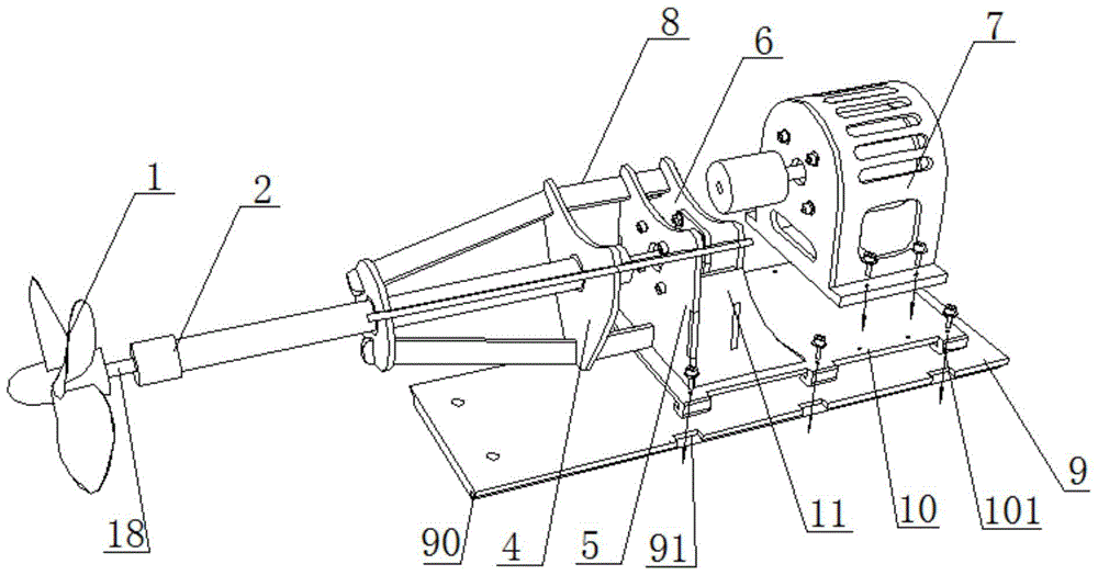
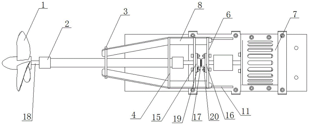
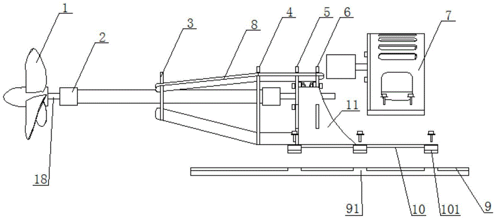
[0029] A motor mounting bracket, comprising a mounting base 10 and a support 7;

[0030] The mounting base 10 is slidably connected to the other side of the support member 7 with a guide rail plate 9, and a position adjustment structure is provided between the mounting base 10 and the guide rail plate 9. The mounting base 10 slides relative to the other side of the motor support member A guide rail plate 9 is connected, and a position adjustment structure is arranged between the installation base 10 and the guide rail plate 9. The position adjustment structure includes a guide rail 90, a detachable and fixed ...


PUM


Abstract

The invention discloses a motor mounting support. The motor mounting support comprises a mounting base and a supporting element. A guide rail plate is in sliding connection with the other side of the mounting base, which is opposite to the motor supporting element. A position regulation structure is arranged between the mounting base and the guide rail plate. The motor mounting support has the advantages of being simple in structure, reasonable in design and capable of regulating the motor mounting position according to actual requirements and improving the dismounting and mounting convenience.

Description

technical field [0001] The present invention relates to the technical field of motor auxiliary devices, and in particular, to a motor mounting bracket. Background technique [0002] Motor refers to an electromagnetic device that realizes electric energy conversion or transmission according to the law of electromagnetic induction. Its main function is to generate driving torque. As a power source, it is usually fixed on the mounting bracket first, and then linked with other components. widely. [0003] Among them, it can be applied to water area survey equipment. For example, the invention application document "An Unmanned Intelligent Survey Vessel" with the application number of 201310705168.8 discloses a propeller propulsion system in its specification. The electric motor is installed in the side cabin of the stern of the underwater buoy through the fixed support, and is connected with the transmission shaft through the coupling, and the propeller is installed at the rear ...

Claims


Application Information

Patent Timeline
Patent Type & Authority Patents(China)
IPC IPC(8): H02K5/26
CPCH02K5/26
Inventor 陈林王化明杜波束建芳陈俊宏屠璐琼李超
Owner ZHEJIANG OCEAN UNIV
Why Eureka
Try Eureka