Cross bar deformation repairing device for railway freight car
A railway freight car and cross-bar technology, which is applied in the field of railway freight car cross-bar deformation repairing devices, can solve the problems of unfavorable device use, large manpower consumption, difficult repair rate and the like
- Summary
- Abstract
- Description
- Claims
- Application Information
AI Technical Summary
Problems solved by technology
Method used
Image
Examples
Embodiment 1
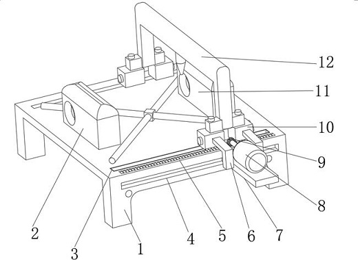
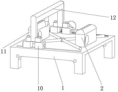
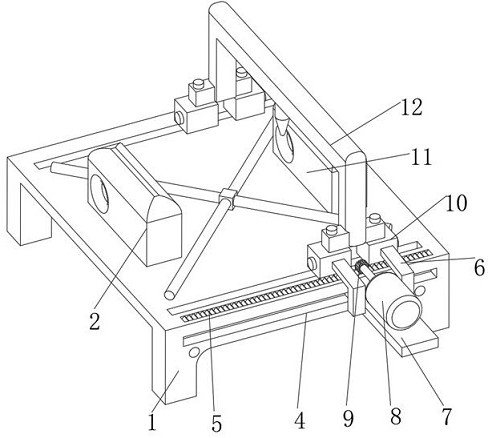
[0023] Embodiment one, with reference to Figure 1-6A device for repairing the deformation of a railway wagon cross bar, comprising a first base 1, the top of the first base 1 is provided with a first chute 3, the bottom of the first chute 3 inner wall is fixedly welded with a support plate 13, the first chute The inner wall of 3 is movably equipped with a roller 23, the outer surface of the roller 23 is fixedly equipped with a slider 22, and the outer surface of the slider 22 is fixedly installed with a scraper 21, and the outer surface of the roller 23 is hung by the scraper 21 to achieve For the purpose of scraping and cleaning the inner wall of the first chute 3, the outer surface of the slider 22 is fixedly inserted with two struts 24, and the outer surface of the two struts 24 is fixedly installed with an ejector plate 20, and the scraper 21 Scrape the garbage on the outer surface of the roller 23 and drop the garbage into the chute again along the top of the ejector pla...
Embodiment 2
[0024] Embodiment two, refer to Figure 1-3 and Image 6 : the outer surface of the first base 1 is provided with a second chute 4, the inner wall of the second chute 4 is movably installed with a base plate 7, the top of the base plate 7 is fixedly installed with a motor 8, and the outer surface of the output end of the motor 8 is fixedly sleeved with a second chute. A gear 9, the top of the first base 1 is provided with a tooth groove 5, so that the output end of the motor 8 can drive the first gear 9 to rotate, the top of the first base 1 is fixedly installed with the first detection box 2, the first base 1 is fixedly installed with a second detection box 11, the outer surface of the second detection box 11 is provided with a through hole, and the inner wall of the through hole is rotatably connected with four pillars 27, and the opposite ends of the four pillars 27 are all fixed Cushions 28 are glued so that the finished product can be fixedly installed on the outer surfa...
PUM
 Abstract
Description
Claims
Application Information
 - R&D
- Intellectual Property
- Life Sciences
- Materials
- Tech Scout
- Unparalleled Data Quality
- Higher Quality Content
- 60% Fewer Hallucinations
Browse by: Latest US Patents, China's latest patents, Technical Efficacy Thesaurus, Application Domain, Technology Topic, Popular Technical Reports.
© 2025 PatSnap. All rights reserved.Legal|Privacy policy|Modern Slavery Act Transparency Statement|Sitemap|About US| Contact US: help@patsnap.com


