Method and device for monitoring an energy feed-in point of an energy supply network

An energy supply and feed-in point technology, applied in the field of energy feed-in points and equipment for monitoring energy supply networks, can solve problems such as difficulties and achieve the effect of avoiding deficiencies

Inactive Publication Date: 2015-03-04
SIEMENS AG
View PDF4 Cites 2 Cited by
  • Summary
  • Abstract
  • Description
  • Claims
  • Application Information

AI Technical Summary

Problems solved by technology

This proves to be difficult if the monitoring devices and / or nodes at the feed-in points are in the range of different operators

Method used


Image

  • Method and device for monitoring an energy feed-in point of an energy supply network
  • Method and device for monitoring an energy feed-in point of an energy supply network

Examples


Embodiment Construction

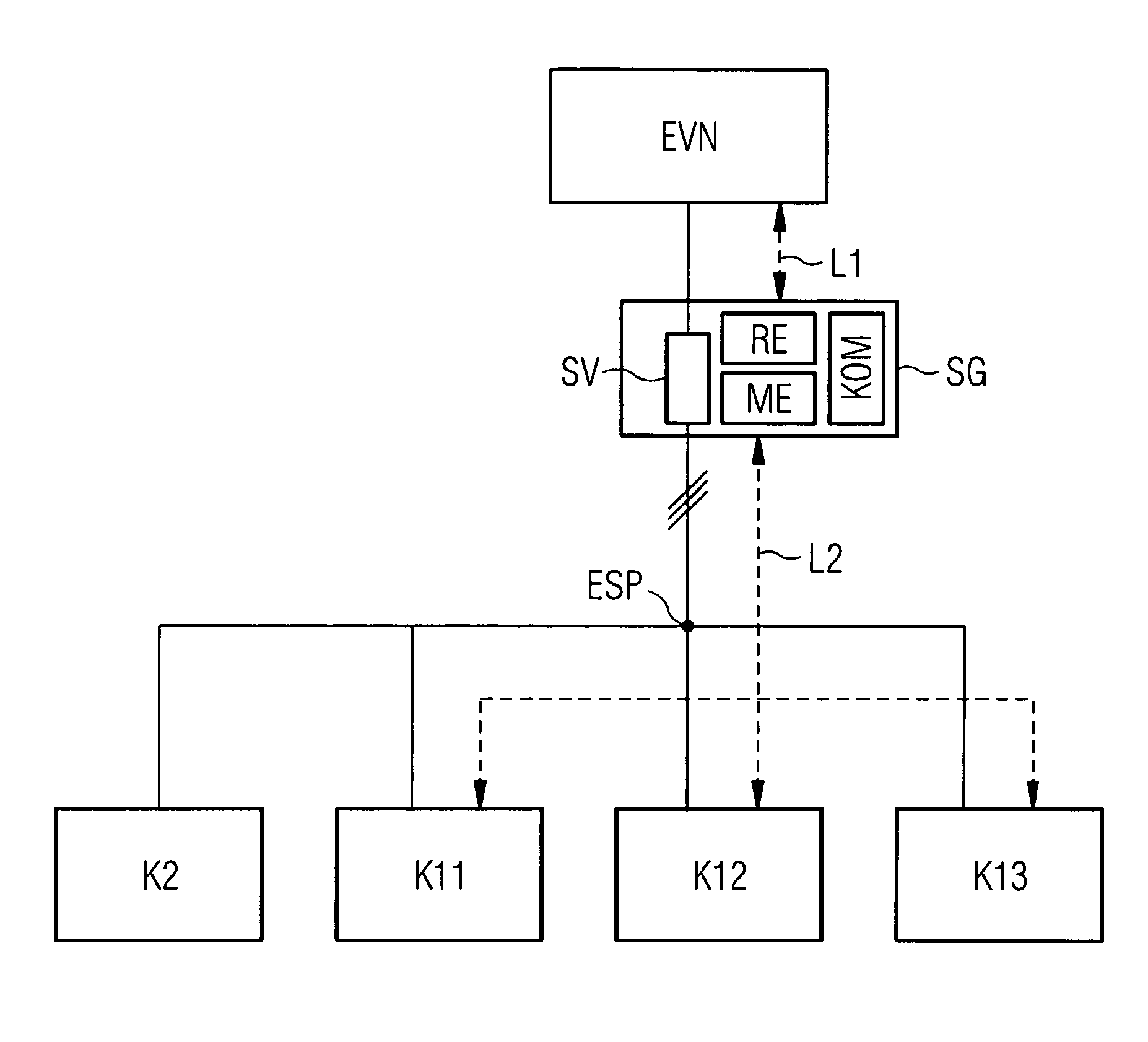
[0038] figure 1 A schematic diagram of a device according to the invention for monitoring an energy feed-in point ESP of an energy supply network EVN is shown. The device is a protective device SG, which can be considered as a combination of a power monitoring device and a protective switch. The protective device SG is arranged between the energy feed-in point ESP and the energy supply network EVN. By way of example only, the line between the protective device SG and the energy feedpoint ESP is configured in three phases, whereby the nodes K11 , K12 , K13 and K2 connected to the energy feedpoint ESP are supplied with a voltage of 400 V, for example. Likewise, the lines connecting the nodes K11 , K12 , K13 , K2 to the protective device SG can be implemented as single-phase. In this case, the nodes K11 , K12 , K13 , and K2 are supplied with a supply voltage of, for example, 230V. The stated voltage values ​​apply to the energy supply network in the low-voltage range in German...


PUM


Abstract

The invention describes a method for monitoring an energy feed-in point (ESP) of an energy supply network (EVN), particularly in the low voltage range, a number of first and second nodes (K11, K12, K13, K2) being connected or connectable to the energy feed-in point, the respective nodes (K11, K12, K13, K2) being an energy producer, an energy consumer or a prosumer. In the method according to the invention, an actual current which represents the current consumption or current output is detected at the energy feed-in point (ESP) by a measuring and monitoring device. A piece of current information (SI) received from one of the first nodes (K11, K12, K13), which represents an intended and / or a maximum possible current consumption or output of the first node (K11, K12, K13), is processed by checking whether a current value in the piece of current information (SI) fulfils a predetermined criterion in respect of a possible current value (MW) of the energy feed-in point (ESP). The possible current value (MW) is determined by a differential formed from the predetermined maximum current of the energy feed-in point (ESP) and the actual current. Finally, depending on whether the criterion at the first node (K11, K12, K13) is fulfilled or not, a message is transferred which confirms or denies the current consumption or output to the first node (K11, K12, K13).

Description

technical field [0001] The invention relates to a method and a device for monitoring an energy feed-in point of an energy supply network, especially in the low-voltage range. A plurality of first and second nodes are connected or can be connected to the energy feed point, wherein the respective nodes are energy generators, energy consumers or dissipators. Background technique [0002] In this description, a first node is a node which has a communication mechanism and can communicate with a device implementing the method. The second node is a node which does not have a communication mechanism and is therefore also not able to communicate with the device implementing the method. [0003] A disproducer is understood to be a component which can both generate energy and feed energy into the energy supply network, and can consume energy and absorb energy from the energy supply network. An example of this is, for example, an electrically operated motor vehicle which draws energy ...

Claims


Application Information

Patent Timeline
IPC IPC(8): H02J3/06H02J3/32H02J3/38
CPCH02J3/381H02J3/32H02J3/06H02J2003/001G05B15/02G05F1/66H02J3/001H02J3/322H02J3/0012H02H7/26
Inventor S.朗格迈尔J.莱茵施克
Owner SIEMENS AG
Why Eureka
Try Eureka