Fire prevention cabinet

A fire cabinet and cabinet technology, which is applied to the ventilation device of the anti-gas shielding part, life-saving equipment, etc., can solve the problems of reducing the surrounding air, no dense smoke, and many temporary buildings, etc., and achieves the reduction of smoke concentration, simple operation, and use. handy effect

Active Publication Date: 2015-03-11
ZHONG HANG TIAN CONSTR ENG COMPANY +1
View PDF9 Cites 3 Cited by
  • Summary
  • Abstract
  • Description
  • Claims
  • Application Information

AI Technical Summary

Problems solved by technology

The potential safety hazards at the construction site are mainly due to the following reasons: weak awareness of fire safety responsibility subjects; non-standard fire source management, inadequate fire safety measures; many temporary buildings with low fire resistance levels; high mobility of construction personnel, cross-operation and Management is chaotic; fire exits are seriously blocked
The construc

Method used


Image

  • Fire prevention cabinet
  • Fire prevention cabinet
  • Fire prevention cabinet

Examples


Embodiment 1

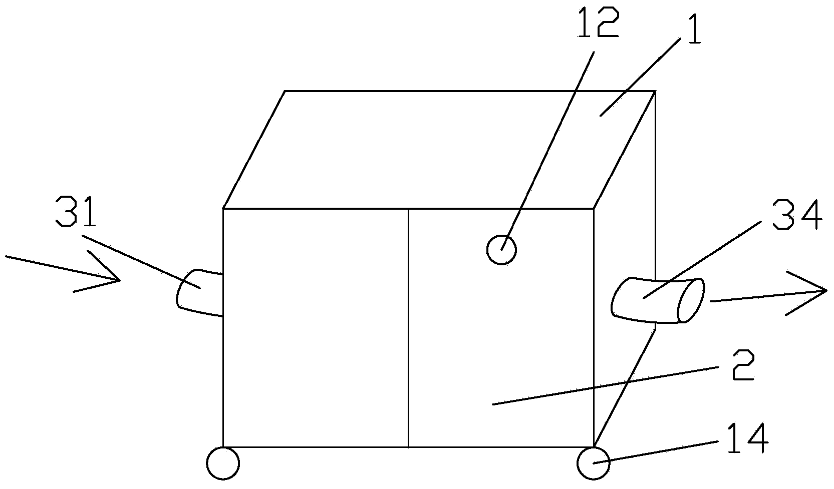
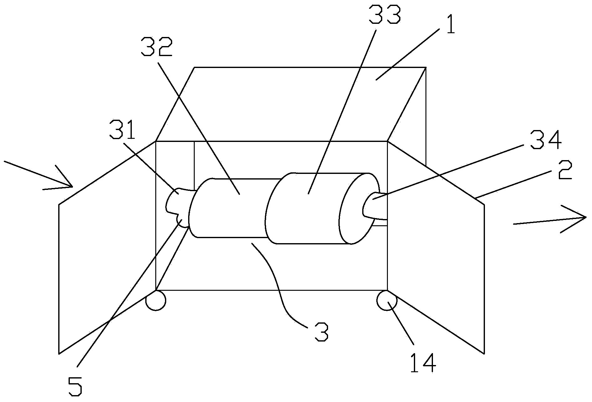
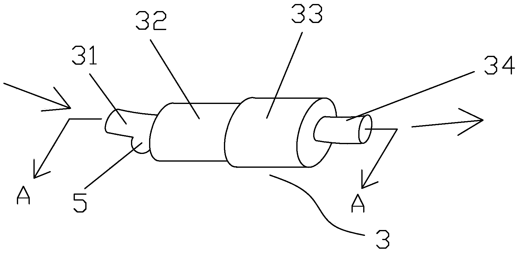
[0035] Fire fighting cabinet of the present invention, as attached Figure 1-4 As shown, 1 is the cabinet body; 2 is the cabinet door; 3 is the suction fan, 31 is the air inlet channel, 32 is the negative pressure air pump, 33 is the air chamber, and 34 is the air outlet channel; 4 is the primary filter; 5 is the Collection tank; 6 is a cleaning brush; 12 is a fire alarm; 14 is a universal wheel.

[0036] Fire fighting cabinet of the present invention, as attached Figure 1-4 As shown, the cabinet body 1 and the cabinet door 2 are included, the cabinet door 2 is provided with a fire alarm 12, the cabinet body 1 is provided with a suction fan 3, and the suction fan 3 is electrically connected with the fire alarm 12; the fire alarm 12 When alarming, the suction fan 3 runs automatically; the suction fan 3 sequentially includes an air inlet duct 31, a negative pressure air pump 32, an air chamber 33 and an air outlet duct 34 along the same axis. One side of the cabinet wall pass...

Embodiment 2

[0038] Fire fighting cabinet of the present invention, as attached Figure 1-3 , shown in 5, 1 is a cabinet; 2 is a cabinet door; 3 is a suction fan, 31 is an air inlet, 32 is a negative pressure air pump, 33 is an air chamber, and 34 is an air outlet; 4 is a primary filter; 5 is a collection tank; 6 is a cleaning brush; 7 is an active carbon adsorption layer; 12 is a fire alarm; 14 is a universal wheel.

[0039] Fire fighting cabinet of the present invention, as attached Figure 1-3 , 5, except that the following structures are different from Embodiment 1, all the others are the same: the air chamber 33 is provided with an activated carbon adsorption layer 7 at the end connected to the negative pressure air pump 32.

Embodiment 3

[0041] Fire fighting cabinet of the present invention, as attached Figure 1-3 , shown in 6, 1 is a cabinet; 2 is a cabinet door; 3 is a suction fan, 31 is an air inlet, 32 is a negative pressure air pump, 33 is an air chamber, and 34 is an air outlet; 4 is a primary filter; 5 is a collection tank; 6 is a cleaning brush; 7 is an activated carbon adsorption layer; 8 is a chemical adsorption layer; 9 is a cavity; 12 is a fire alarm; 14 is a universal wheel.

[0042] Fire fighting cabinet of the present invention, as attached Figure 1-3 , 6, except that the following structures are different from Example 2, all the others are the same: a chemical adsorption layer 8 is also arranged in the gas chamber 33, and the chemical adsorption layer 8 and the activated carbon adsorption layer 7 form a cavity 9.


PUM


Abstract

The invention relates to a fire prevention cabinet which comprises a cabinet body and a cabinet door, wherein the cabinet door is provided with a fire alarm; the cabinet body is internally provided with a suction ventilator; the suction ventilator is electrically connected with the fire alarm; when the fire alarm gives an alarm, the suction ventilator automatically runs. The fire prevention cabinet is convenient to use and easy to operate; the fire prevention cabinet is provided with the suction ventilator, thus being capable of absorbing the dense smoke produced by a fire, purifying the air, reducing the temperature of the ambient air and controlling the fire behavior.

Description

technical field [0001] The invention relates to a fire-fighting appliance, in particular to a fire-fighting cabinet. Background technique [0002] The construction site is a place where fires frequently occur, and fire safety work is very important. The potential safety hazards at the construction site are mainly due to the following reasons: weak awareness of fire safety responsibility subjects; non-standard fire source management, inadequate fire safety measures; many temporary buildings with low fire resistance levels; high mobility of construction personnel, cross-operation and The management is chaotic; the fire exits are seriously blocked. The construction site usually needs to set up fire fighting cabinets in the working, living and production areas. Usually, the existing fire fighting cabinets only have fire extinguishers, fire sand, fire buckets, fire axes, shovels, fire hoses and other fire fighting facilities, and there is no fire that can absorb the fire. Smoke...

Claims


Application Information

Patent Timeline
IPC IPC(8): A62B13/00
Inventor 于立民叶丽影杨明李晓亮徐伟孙锐彭荣康郭林华杨晓辰段治强李明阳周超杨少飞付光磊何广杰张萌金若翔于东杰
Owner ZHONG HANG TIAN CONSTR ENG COMPANY
Why Eureka
Try Eureka