An h-shaped girder welding deformation control device

A control device and welding deformation technology, applied in welding equipment, manufacturing tools, metal processing equipment, etc., can solve problems such as welding corner deformation of H-shaped girders, achieve the effects of reducing residual stress, increasing friction, and reducing orthopedic procedures

Active Publication Date: 2016-11-09
SHANGHAI JIAOTONG UNIV
View PDF10 Cites 0 Cited by
  • Summary
  • Abstract
  • Description
  • Claims
  • Application Information

AI Technical Summary

Problems solved by technology

However, these methods do not currently have methods and devices for welding angle deformation and torsional deformation of H-shaped girders.

Method used


Image

  • An h-shaped girder welding deformation control device
  • An h-shaped girder welding deformation control device
  • An h-shaped girder welding deformation control device

Examples


Embodiment 1

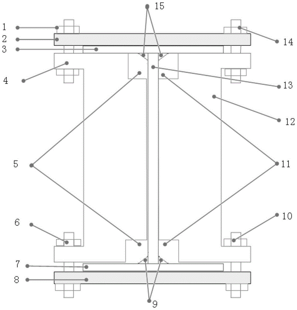
[0042] An H-shaped girder welding deformation control device, its structure is as follows figure 1 As shown, it mainly includes an upper platen 2 connected to the upper surface of the upper wing plate 3, a left platen 4 and a right platen 12 symmetrically connected to both sides of the web 13, and a lower platen 8 connected to the lower surface of the lower wing plate 7. The left pressing plate 4 and the right pressing plate 12 are respectively connected with the upper pressing plate 2 and the lower pressing plate 8 through the upper left screw 1, the lower left screw 6, the upper right screw 14, and the lower right screw 10, thereby controlling the positions of the upper wing plate 3 and the lower wing plate 7 during welding There will be no angular deformation, and the inner sides of the left pressing plate 4 and the right pressing plate 12 are set on the left and right sides of the web 13 . A left welding process hole 5 and a right welding process hole 11 are provided at th...

Embodiment 2

[0055] The above-mentioned device is used to control the welding deformation of the H-shaped girder, and its basic dimensions are: the upper and lower wing plate dimensions: length 1200mm, width 70mm, thickness 6.0mm. Web size: length 1200mm, height 144mm, 6.0mm. Welding method: manual welding, no false welding exists. Under the action of the deformation control device, the geometric dimensions of the H-shaped girder basically do not change.

Embodiment 3

[0057] H-shaped girder-QSTE700 welding deformation control

[0058] The above-mentioned device is used to control the welding deformation of the H-shaped girder. The basic dimensions are: the upper and lower flange dimensions: length 400mm, width 50mm, thickness 4.0mm. Web size: length 400mm, height 76mm, 4.0mm. Welding method: manual welding, no false welding exists. Under the action of the deformation control device, the welding deformation of the H-shaped girder composed of 700MPa high-strength steel plates is well controlled.

[0059] The patented method and device of the present invention can be used to realize the control of the H-shaped girder during the welding deformation process, ensure the size and assembly accuracy of the H-shaped girder after welding, reduce unnecessary post-weld correction procedures, and can be widely used in similar structures. In welding deformation control, it has important reference application value for welding auxiliary positioning and p...


PUM


Abstract

The invention relates to an H-girder welding deformation control device. The H-girder welding deformation control device comprises an upper press plate connected to the upper surface of an upper wing plate, a left press plate, a right press plate and a lower press plate connected to the lower surface of a lower wing plate, wherein the left press plate and the right press plate are symmetrically connected to two sides of a web plate, are connected with the upper press plate and the lower press plate through connecting screws and control the positions of the upper wing plate and the lower wing plate not to produce angle deformation, and the inner sides of the left press plate and the right press plate abut against the left side face and the right side face of the web plate. Compared with the prior art, the H-girder welding deformation control device achieves accurate size after workpiece deformation in the welding process, ensures assembly tolerance of a workpiece, decreases follow-up shape correction work procedures, reduces heat source input and avoids the influence on parent material performance.

Description

technical field [0001] The invention belongs to the technical field of automobile manufacturing, and in particular relates to an H-shaped girder welding deformation control device. Background technique [0002] The modern automotive industry has higher and higher requirements for lightweight, safety, exhaust emissions, cost control and fuel economy, which drives the automotive industry to adopt high-strength steel plates and some high-strength lightweight materials. The car frame is an important load-bearing part of the car. According to statistics, the mass of the car body accounts for about 40%-60% of the car's own quality. The light weight of its structure is of great significance to the energy saving and environmental protection of the car. The H-shaped girder is the main component of the automobile frame, and the H-shaped girder composed of high-strength steel plates instead of traditional steel plates can realize the weight reduction of the frame. The H type is mainly...

Claims


Application Information

Patent Timeline
Patent Type & Authority Patents(China)
IPC IPC(8): B23K31/00
CPCB23K31/003
Inventor 但文蛟刁可山张卫刚刘飞缑瑞宾
Owner SHANGHAI JIAOTONG UNIV
Why Eureka
Try Eureka