Compensation Method for Defects in Milling and Grinding of High Precision Aspheric Surface

A compensation method and aspheric surface technology, which is applied to metal processing equipment, optical surface grinders, and parts of grinding machine tools, etc., can solve the problems that the detection data cannot be measured in the whole process and affect the correction effect, so as to eliminate the central boss or Over-cutting, more reasonable workpiece surface shape, and good workpiece surface shape

Active Publication Date: 2017-01-04
SHANGHAI MODERN ADVANCED ULTRA PRECISION MFG CENT
View PDF7 Cites 0 Cited by
  • Summary
  • Abstract
  • Description
  • Claims
  • Application Information

AI Technical Summary

Problems solved by technology

However, this approach is only to correct the curve in theory, and there will be deviations from the curve required in actual processing. Since the detection data cannot be measured in the whole process, how to find a reliable end point of the program, that is, the center of rotation of the workpiece, has become an influence. One major cause of the correction effect

Method used


Image

  • Compensation Method for Defects in Milling and Grinding of High Precision Aspheric Surface
  • Compensation Method for Defects in Milling and Grinding of High Precision Aspheric Surface
  • Compensation Method for Defects in Milling and Grinding of High Precision Aspheric Surface

Examples


Embodiment Construction

[0034] Below in conjunction with embodiment and accompanying drawing, the present invention is described in detail, present embodiment implements under the premise of technical solution of the present invention, has provided detailed embodiment and specific operation process, but protection scope of the present invention is not limited to Examples described below.

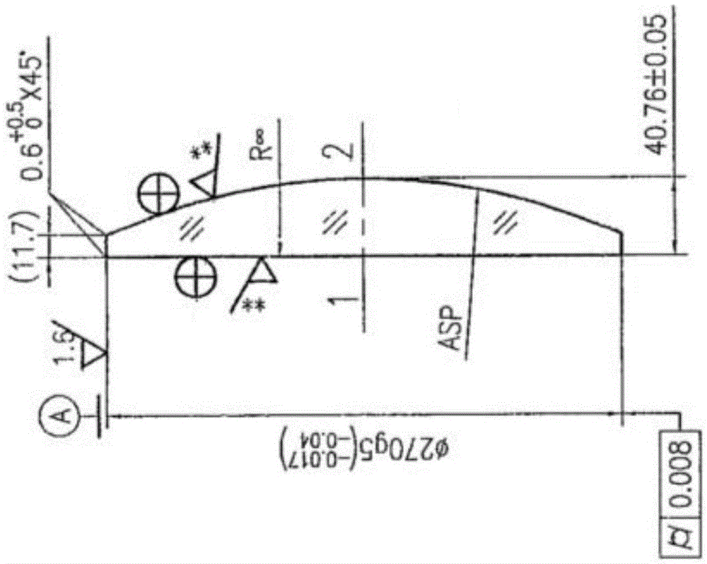
[0035] figure 1 It is an embodiment diagram of an aspherical workpiece to be processed, and the formula of the aspheric surface is as follows:

[0036] Z = c · r 2 1 + 1 - ( 1 + k ) · c 2 · r 2 ; ...


PUM


Abstract

A method for compensating for defects in high-precision aspheric milling and grinding, including processing the aspheric surface to be processed with a standard equation; using a profiler to detect the surface shape of the workpiece processed by the standard equation, and selecting the aspheric surface closest to the requirements of the drawing The radius value is used to adjust the positive and negative of the Y-axis direction of the tool; the profiler is used to detect the surface shape of the workpiece processed by the standard equation, and the detected deviation curve is observed to adjust the positive and negative of the X-axis direction of the tool; the present invention is effective Eliminate the center boss or overcut phenomenon caused by the error of the detection data, so that the surface shape of the workpiece becomes better and more reasonable, and meets the technical requirements.

Description

technical field [0001] The invention relates to the technical field of ultra-precision machining and measurement, in particular to a method for compensating defects in high-precision aspheric milling and grinding. Background technique [0002] Milling and grinding machines process high-precision surface-type aspheric surfaces. At present, the method of processing from the edge to the center is generally used. Due to various reasons, it is often encountered that a small boss appears in the center of the workpiece. Once the boss is vibrated or the stress generated when the grinding wheel leaves, the small boss will be broken, thus forming a pit or even crack. Sometimes, there will be overcutting, that is, cutting off the apex of the workpiece to form a small platform, which will affect the initial height of the workpiece. At the same time, the grinding surface of the grinding wheel is an arc, so it is also possible to form a protruding cone, which will also affect the origina...

Claims


Application Information

Patent Timeline
Patent Type & Authority Patents(China)
IPC IPC(8): B24B13/00B24B41/00B24B49/16
Inventor 陈静刘天豪
Owner SHANGHAI MODERN ADVANCED ULTRA PRECISION MFG CENT
Why Eureka
Try Eureka