
Sliding rod available for being positioned

A sliding rod and chute technology, applied in the field of feeding, can solve the problems of inconvenient unlocking of the sliding rod and few locking positions.

Inactive Publication Date: 2015-03-11
重庆市南川区泰城钢化玻璃制品有限责任公司
View PDF0 Cites 12 Cited by
  • Summary
  • Abstract
  • Description
  • Claims
  • Application Information

AI Technical Summary

Problems solved by technology

[0004] The invention provides a sliding bar that can be positioned to solve the problems of inconvenient unlocking and too few locking positions of the existing sliding bar

Method used


Image

  • Sliding rod available for being positioned

Examples


Embodiment Construction

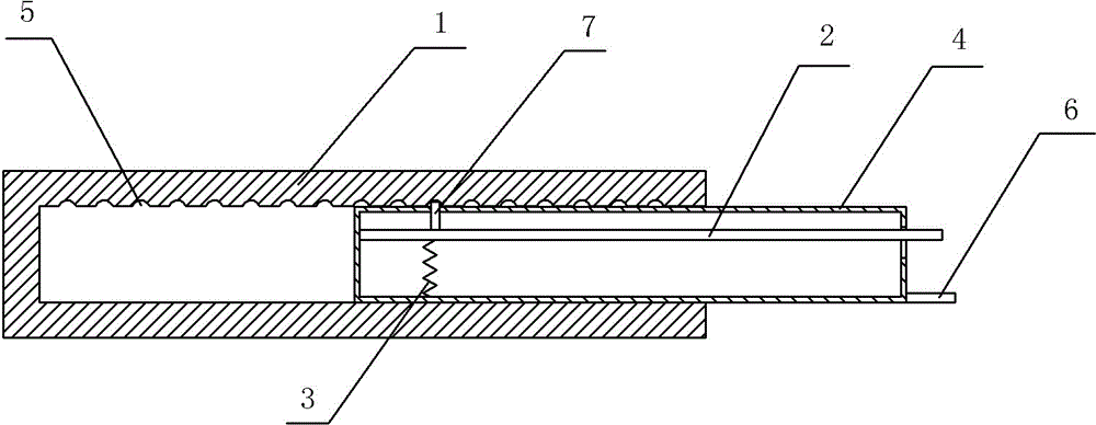
[0014] The reference signs in the drawings of the description include: chute 1 , unlocking lever 2 , return spring 3 , slide bar body 4 , groove 5 , handle 6 , and pin rod 7 .

[0015] like figure 1 As shown, a slide bar that can be positioned in this embodiment includes a slide slot 1 , an unlocking lever 2 , a return spring 3 and a slide bar body 4 slidably connected in the slide slot 1 . The side inner wall of the chute 1 is provided with 17 grooves 5 along its length direction, the slide bar body 4 is a hollow structure, the right end of the slide bar body 4 is open, and the right end is also provided with a handle 6. There is a through hole on the side, and one end of the unlocking lever 2 is fixed on the inner wall of the slide bar body 4 , and the other end protrudes from one end of the slide bar body 4 opening. A pin 7 is fixed on the unlocking lever 2, and the top of the pin 7 is provided with a rubber sleeve. In a natural state, the pin 7 passes through the through ...


PUM


Abstract

The invention discloses a sliding rod available for being positioned. The sliding rod comprises a sliding groove, a sliding rod body in sliding connection to the sliding groove, and an unlocking rod, wherein multiple concave grooves are formed in the inner wall of the side face of the sliding groove along the length direction of the sliding groove; the sliding rod body is of a hollow structure; one end of the sliding rod body is in an opening shape; a through hole is formed in the side face of the sliding rod body; one end of the unlocking rod is fixedly arranged on the inner wall of the sliding rod body; the other end of the unlocking rod stretches out from the opening of the sliding rod body; a pin rod is fixedly arranged on the unlocking rod; the pin rod penetrates through the through hole, and is exposed to the sliding rod body; the height, exposed to the sliding rod body, of the pin rod corresponds to the offset of the unlocking rod. According to the sliding rod, when the unlocking rod is pressed down, and the pin rod completely retracts into the sliding rod body, unlocking can be realized; the movement of the sliding body can be realized in a push or pull way; the unlocking of the sliding rod body can be realized quite conveniently by one hand or one mechanism; as the multiple concave grooves are formed in the inner wall of the side face of the sliding groove along the length direction of the sliding groove, locking at multiple points can be realized; therefore the sliding rod is applicable for multiple working conditions in production.

Description

technical field [0001] The invention belongs to the technical field of feeding. Background technique [0002] The sliding rod refers to a rod body that can slide in a certain direction, and the existing sliding rod can slide freely in the chute. In order to realize the locking of the sliding bar, there is a groove on the sliding bar, and a through hole is opened on the chute connected with the sliding bar, and the fixing pin is in the through hole, and the fixing pin is connected with a compression spring. When the groove passes through the fixed pin, the fixed pin will fall into the groove under the action of the elastic force of the stage clip, and the slide bar will be blocked and cannot move. [0003] When unlocking the slide bar, it is necessary to pull out the slide bar while the fixing pin is raised. When the fixed pin is far away from the hand-held end of the slide bar and it is manually operated, one person needs to lift the fixed pin and the other pulls out the s...

Claims


Application Information

Patent Timeline
Patent Type & Authority Applications(China)
IPC IPC(8): F16B7/14
CPCF16B7/1472
Inventor 韩国才
Owner 重庆市南川区泰城钢化玻璃制品有限责任公司
Features
  • Generate Ideas
  • Intellectual Property
  • Life Sciences
  • Materials
  • Tech Scout
  • Unparalleled Data Quality
  • Higher Quality Content
  • 60% Fewer Hallucinations
Learn More