A power battery pack and its protective conductive plate
A technology of power battery packs and conductive plates, which is applied to battery pack parts, secondary battery manufacturing, circuits, etc., can solve problems such as explosion, battery damage, and combustion, and achieve the goal of preventing diffusion, protecting safety, and ensuring anti-vibration capabilities Effect
- Summary
- Abstract
- Description
- Claims
- Application Information
AI Technical Summary
Problems solved by technology
Method used
Image
Examples
Embodiment 1
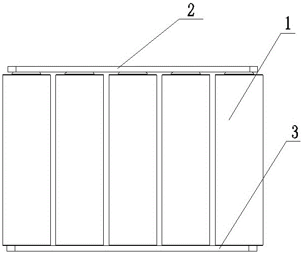
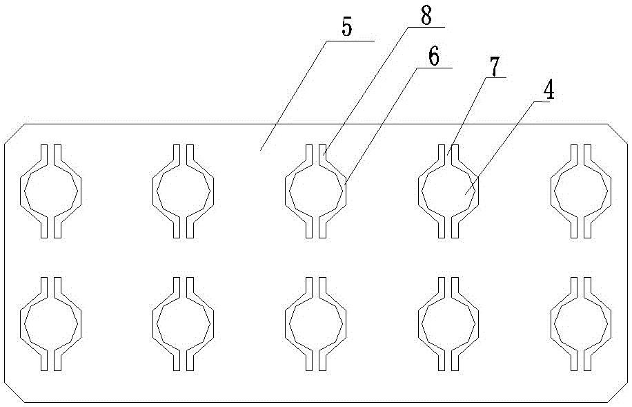
[0022] Such as figure 1 with 2 As shown, a power battery pack, the battery includes several single cells 1 arranged in a matrix and connected in parallel, the positive and negative electrodes of the battery are respectively connected with a positive conductive sheet 2 and a negative conductive sheet 3, the positive conductive The thin plate 2 is a protective conductive plate. The protective conductive plate includes a plate body 5 and several electrode connecting pieces 4 arranged in a matrix. Each electrode connecting piece 4 is connected to the electrodes of each single battery. The left and right sides of the electrode connecting pieces There are two isolation grooves symmetrically, and the isolation grooves include a semi-circular groove 6 and a linear groove 8 arranged at both ends of the semi-circular groove. The electrode connecting piece 4 forms two slender flat belts between the linear grooves 8 on the left and right sides. 7. The electrode connecting piece 4 is elec...
Embodiment 2
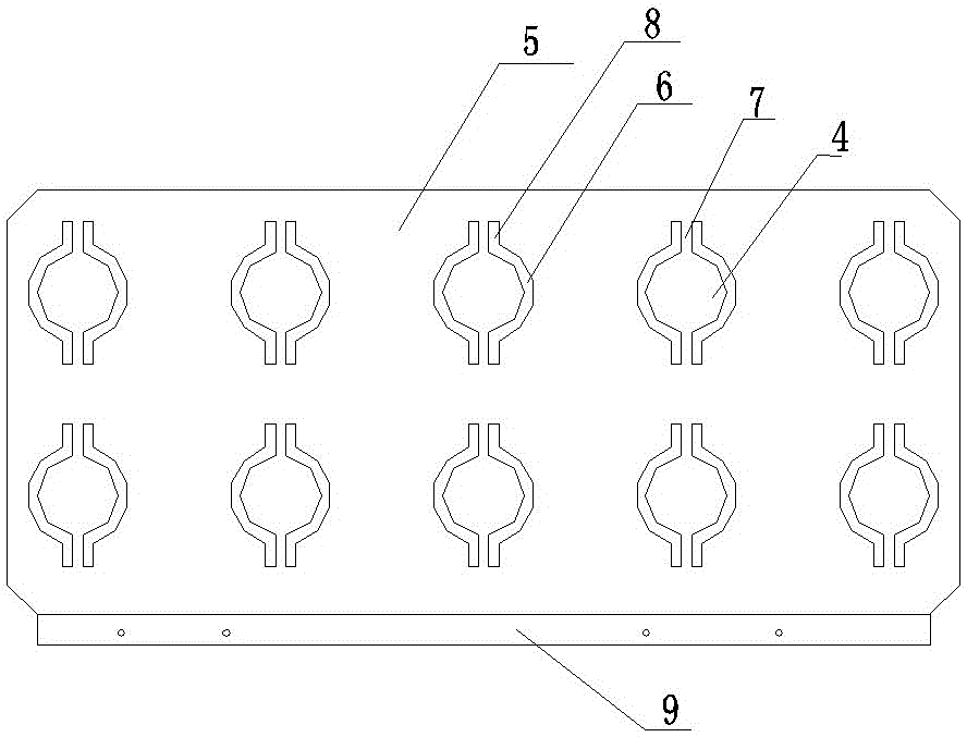
[0026] Such as figure 1 with 3 As shown, a power battery pack, the battery includes several single cells 1 arranged in a matrix and connected in parallel, the positive and negative electrodes of the battery are respectively connected with a positive conductive sheet 2 and a negative conductive sheet 3, the negative conductive sheet The thin plate 3 is a protective conductive plate. The protective conductive plate includes a plate body 5 and several electrode connecting pieces 4 arranged in a matrix. Each electrode connecting piece 4 is connected to the electrodes of each single battery. The left and right sides of the electrode connecting pieces There are two isolation grooves symmetrically, and the isolation grooves include a semi-circular groove 6 and a linear groove 8 arranged at both ends of the semi-circular groove. The electrode connecting piece 4 forms two slender flat belts between the linear grooves 8 on the left and right sides. 7. The electrode connecting piece 4 i...
Embodiment 3
[0031] Such as figure 1 with 3 As shown, a power battery pack, the battery includes several single cells 1 arranged in a matrix and connected in parallel, the positive and negative electrodes of the battery are respectively connected with a positive conductive sheet 2 and a negative conductive sheet 3, the positive conductive The thin plates 2 and the negative conductive thin plates 3 are all protective conductive plates, and the protective conductive plates include a plate body 5 and a plurality of electrode connecting pieces 4 arranged in a matrix, each electrode connecting piece 4 is connected to the electrodes of each single battery, and the electrodes Two isolating grooves are symmetrically arranged on the left and right sides of the connecting sheet, and the isolating grooves include a semi-annular groove 6 and a linear groove 8 arranged at both ends of the semi-annular groove. An elongated flat strip 7, through which the electrode connecting piece 4 is electrically con...
PUM
| Property | Measurement | Unit |
|---|---|---|
| area | aaaaa | aaaaa |
| current | aaaaa | aaaaa |
| thickness | aaaaa | aaaaa |
Abstract
Description
Claims
Application Information
 - R&D
- Intellectual Property
- Life Sciences
- Materials
- Tech Scout
- Unparalleled Data Quality
- Higher Quality Content
- 60% Fewer Hallucinations
Browse by: Latest US Patents, China's latest patents, Technical Efficacy Thesaurus, Application Domain, Technology Topic, Popular Technical Reports.
© 2025 PatSnap. All rights reserved.Legal|Privacy policy|Modern Slavery Act Transparency Statement|Sitemap|About US| Contact US: help@patsnap.com


