Humidifier for respiratory apparatus

A technology of breathing device and humidifier, which is applied in the direction of respiratory protection device, respirator, breathing mask, etc., can solve the problems such as the inability to provide high-humidity airflow and the inability of users to breathe air comfortably.

Active Publication Date: 2015-03-18
APEX MEDICAL CORPORATION
View PDF4 Cites 3 Cited by
  • Summary
  • Abstract
  • Description
  • Claims
  • Application Information

AI Technical Summary

Problems solved by technology

In addition, humidifiers in the prior art cannot provide a high humid

Method used


Image

  • Humidifier for respiratory apparatus
  • Humidifier for respiratory apparatus
  • Humidifier for respiratory apparatus

Examples


Embodiment Construction

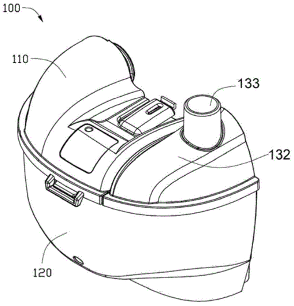
[0076] A specific embodiment of a humidifier will be described in detail below in conjunction with the drawings.

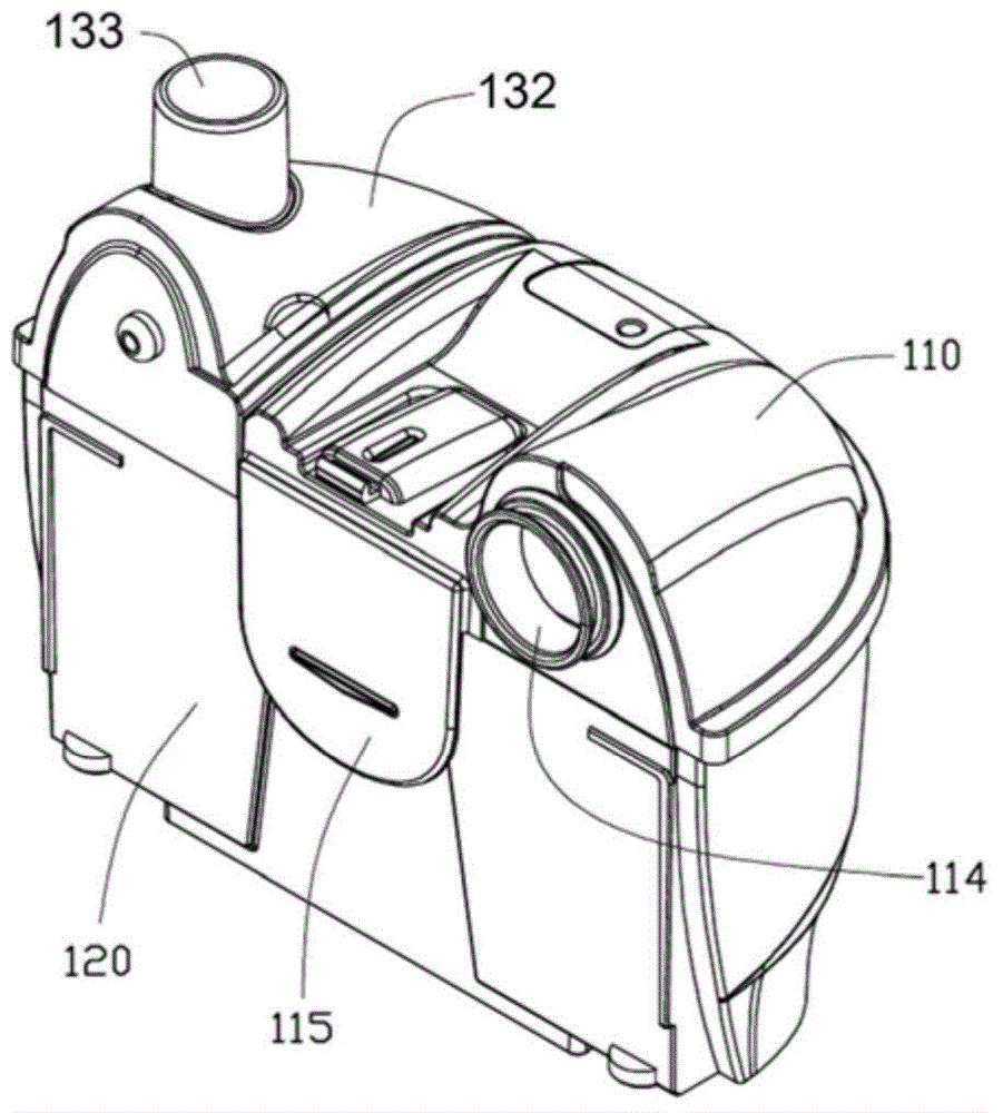
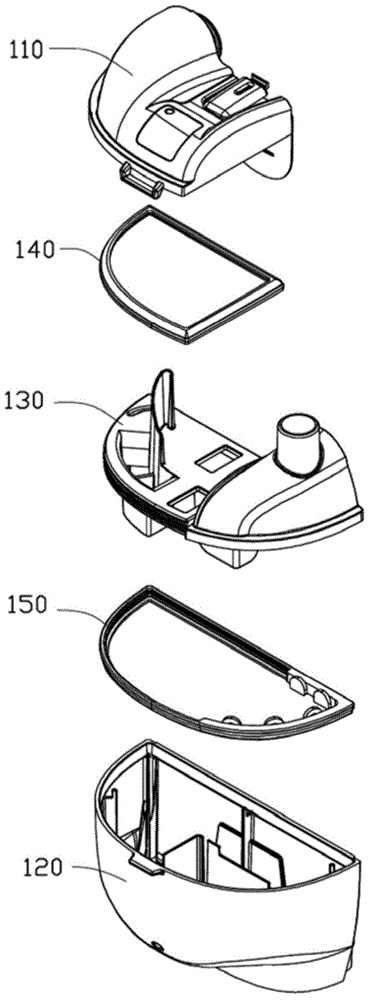
[0077] refer to Figure 1 to Figure 3 , which shows the structure of a specific embodiment of the humidifier 100 . The humidifier 100 includes a first cover 110 , a second cover 120 , a partition 130 , a first gasket 140 and a second gasket 150 .

[0078] refer to Figure 4 and Figure 5 , the first cover 110 defines a first chamber 111 and a second chamber 112 . The first chamber 111 is separated from the second chamber 112 by a first partition 113 . When the first cover 110 is combined with the partition plate 130 , the first partition plate 113 adjoins, abuts or at least partially contacts the partition plate 130 , and substantially separates the first chamber 111 and the second chamber 112 . An air inlet 114 is defined on a side of the first cover 110 and communicates with the first chamber 111 . The air inlet 114 is used to communicate with the air blow...


PUM


Abstract

A humidifier for a respiratory apparatus includes a first cover, a second cover engaged with the first cover and a partition plate. The first cover defines an air inlet. The second cover defines a chamber configured to contain at least some amount of water. A heater is configured to heat the water to generate humidified air in the chamber. The partition plate is partly sandwiched between the first cover and the second cover. The partition plate defines an air outlet. Air input via the air inlet is humidified by being mixed with the humidified air and thereafter ejected through the air outlet. The air entering via the air inlet is divided by the partition plate into a plurality of flows having different flow velocities, thereby forming a plurality of flow paths.

Description

technical field [0001] The present invention relates to a humidifier, in particular to a humidifier for breathing apparatus. Background technique [0002] A humidifier is a device used to provide breathable air to a user. The air inlet of the humidifier is connected with the blower, and the air outlet of the humidifier is connected with the breathing mask. The air from the blower is humidified in the humidifier and delivered to the respirator via the air delivery tube. A humidifier usually includes a first cover, a second cover and a partition. The first cover defines an air inlet for air to enter and an air outlet for air to flow out. The second cover includes some water chamber. A heating plate is embedded in the bottom of the chamber to heat the water to generate humidified air. The air from the air inlet is mixed with the humidified air to be humidified and sent out of the humidifier through the air outlet. The partition plate is located between the first cover and...

Claims


Application Information

Patent Timeline
IPC IPC(8): A62B9/00
CPCA61M16/109A61M16/16A61M2205/3653A61M16/06A61M2206/14A61M2205/123
Inventor 萧家祥简志燦许英杰张明正陈信伟沈文斌林舒淇卢怡甄
Owner APEX MEDICAL CORPORATION
Why Eureka
Try Eureka