Circuit breaker and adapter for a circuit breaker

A technology for protection switches and adapters, which is applied to parts of protection switches, protection switches, and operation/release mechanisms of protection switches, etc., which can solve problems such as failure of motor quality assurance requirements, mismatch of current traces, and damage to circuits.

Inactive Publication Date: 2015-09-16
ELLENBERGER & POENSGEN GMBH
View PDF5 Cites 2 Cited by
  • Summary
  • Abstract
  • Description
  • Claims
  • Application Information

AI Technical Summary

Problems solved by technology

Usually there is not enough space for such a structural embedding, or the current traces of the possible printed circuit board with the fuse holder installed do not correspond to the receptacles of the circuit breaker holder
In addition, for such structural embedding may damage other components of the circuit, or may void the manufacturer's warranty claims on the motor

Method used


Image

  • Circuit breaker and adapter for a circuit breaker
  • Circuit breaker and adapter for a circuit breaker
  • Circuit breaker and adapter for a circuit breaker

Examples


Embodiment Construction

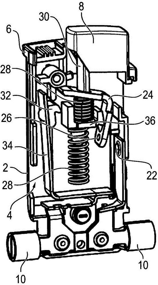
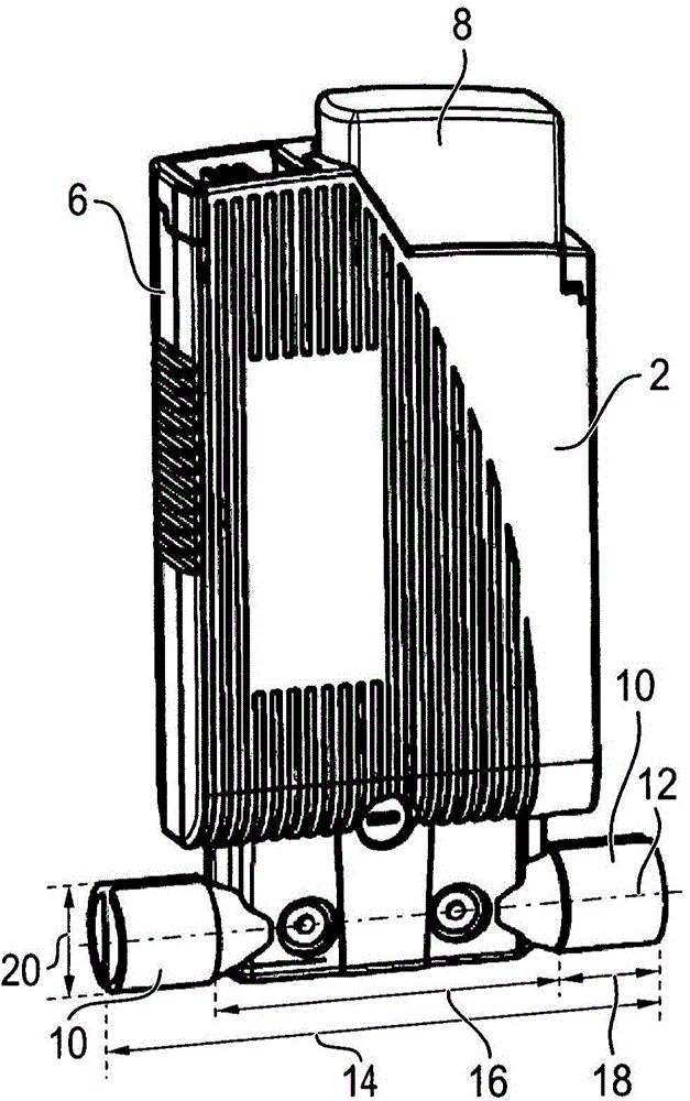
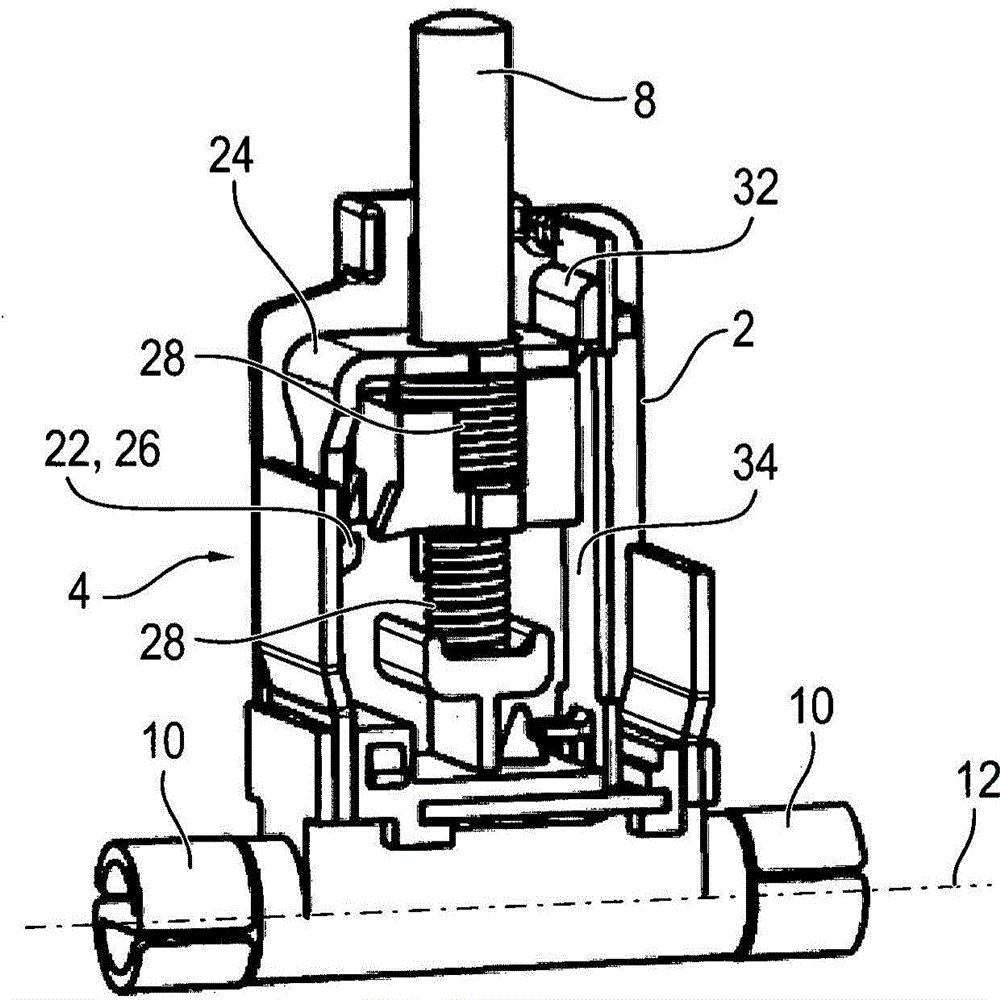
[0030] exist Figure 1a and Figure 1b A first embodiment of the protective switch 2 is shown three-dimensionally in the middle, wherein, in Figure 1a The part of the housing 6 covering the area of ​​the switch lock 4 is removed. In the assembled state, the protective switch 2 serves to protect circuits, in particular electrical lines and / or consumers, such as, for example, electric motors, against overvoltages and / or overcurrents. Protruding from the housing 6 on one side is a manual trigger 8 via which the switch lock 4 can be actuated. On the side of the housing 6 opposite the manual trigger 8 there are two hollow-cylindrical coupling points 10 made of bent metal strips. In other words, the connection locations 10 are stamped and bent parts, wherein the cross-section of each connection location 10 is substantially S-shaped. The cross section is here perpendicular to the axis 12 on which the two coupling points 10 lie.

[0031] The maximum distance 14 between two connect...


PUM


Abstract

The invention relates to a circuit breaker (2) for protecting an electric circuit, comprising a housing (6) and an adapter (84) having a receiving connector (86) for a circuit breaker (2), and two electrically conductive, substantially cylinder-shaped connection points (10) which are positioned along an axis (12). Either the outer diameter (20) of the connection points (10) is between 5.0 mm and 5.3 mm and the maximum distance (14) between the connection points (10) is between 19.0 mm and 21,0 mm, or the outer diameter (20) of the connection points (10) is between 6.2 mm and 6.5 mm and the maximum distance (14) between the connection points (10) is between 30.5 mm and 33.0 mm.

Description

technical field [0001] The invention relates to a protection switch and an adapter for the protection switch Background technique [0002] Electrical devices, such as power supply components or switchboards in machine and plant construction, for example, are protected against overcurrent by means of so-called G fuses, wherein the fuse is designed as a blown fuse. A distinction is made here between very fast, fast, medium, slow and very slow fuse inserts, which differ in their triggering characteristics. Thus, fast fuses are triggered already with relatively short current peaks, whereas slow fuses are effective in the case of relatively long-lasting overload currents, so that, for example, the circuit can be operated without interrupting the circuit. Enables operation of the electric motor and the resulting current peaks. [0003] After the fuse has tripped, it must be replaced and replaced by a new one in order to be able to re-establish the flow of current in the protecte...

Claims


Application Information

Patent Timeline
Patent Type & Authority Applications(China)
IPC IPC(8): H01H73/30H01H73/20
CPCH01H73/30H01H2085/207H01H73/20H01H85/0418H01H71/08H01H71/16H01H71/24H01H2071/088H01H71/02
Inventor 埃里克·菲舍尔
Owner ELLENBERGER & POENSGEN GMBH
Why Eureka
Try Eureka