
Siding rail assembly and operating method thereof

A technology of slide rail assembly and operation method, used in furniture parts, home appliances, drawers, etc.

Active Publication Date: 2017-08-11
KING SLIDE WORKS CO LTD +1
View PDF13 Cites 2 Cited by
  • Summary
  • Abstract
  • Description
  • Claims
  • Application Information

AI Technical Summary

Problems solved by technology

[0003] However, if the operator wishes to temporarily hold the second rail of the slide rail assembly in the fully extended position relative to the first rail, this type of slide rail assembly cannot meet this specific need.

Method used


Image

  • Siding rail assembly and operating method thereof
  • Siding rail assembly and operating method thereof
  • Siding rail assembly and operating method thereof

Examples


Embodiment Construction

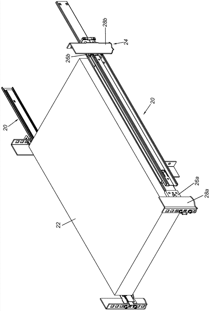
[0041] figure 1 A pair of slide rail assemblies 20 showing an embodiment of the present invention can be used to mount a load 22 to a rack 24 . Specifically, each slide rail assembly 20 can be mounted on a first column 28a and a second column 28b of the frame 24 by means of a first bracket 26a and a second bracket 26b. Since this part is a technical category that can be understood by those who are familiar with the field, for the sake of brevity, details are not repeated here.

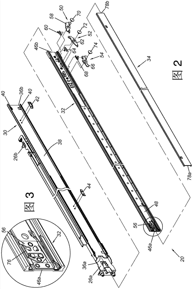
[0042] As shown in FIG. 2 , the slide rail assembly 20 includes a first rail 30 , a second rail 32 and a third rail 34 . The first rail 30 is provided with the above-mentioned first bracket 26a and second bracket 26b. The first rail 30 has a front end 36a, a rear end 36b, and a first channel 38 located between the front end 36a and the rear end 36b. Preferably, the first rail 30 has at least one contact portion 40, such as two protrusions, located adjacent to the rear end 36b. In this embodiment, t...


PUM


Abstract

The invention relates to a siding rail assembly. The siding rail assembly comprises a first rail, a second rail, a third rail and a latch mechanism. The second rail can move relative to the first rail, and the third rail can move relative to the second rail. The latch mechanism is movably installed on the second rail. When the second rail moves relative to the first rail towards a first direction to a second position from a first position, and the third rail moves relative to the second rail towards the first direction to a third position beyond the second rail, a first length is defined by the first rail, the second rail and the third rail. When the second rail moves towards a second direction to a fourth position from the second position, the first length can be shortened to a second length, and the second rail is made to be located at the fourth position relative to the first rail by means of the latch mechanism. The invention further provides an operating method of the sliding rail assembly.

Description

technical field [0001] The invention relates to a slide rail assembly, in particular to a rail member capable of shortening the extension length of the slide rail assembly to facilitate loading and unloading of the slide rail assembly in a limited environmental space. Background technique [0002] Generally speaking, the slide rail assembly usually includes at least two or more rail members, and these rail members can move and displace relative to each other, so that the slide rail assembly has an extended or retracted state. Among them, taking a three-section slide rail assembly with a first rail, a second rail, and a third rail as an example, usually when the second rail and the third rail are displaced in one direction relative to the first rail, they are completely In the extended state, the slide rail assembly has a fully extended length. At the fully extended length, the second rail is generally capable of maintaining a fully extended position relative to the first ra...

Claims


Application Information

Patent Timeline
IPC IPC(8): A47B88/40
CPCA47B2210/0064
Inventor 陈庚金杨顺和卢筱涵王俊强
Owner KING SLIDE WORKS CO LTD
Learn More