
Cross beam riveting clamp
A technology for riveting fixtures and beams, which is applied in the field of riveting fixtures for heavy-duty truck beams. It can solve the problems of unguaranteed assembly size, heavy work intensity of operators, and low degree of automation, and achieve the effects of high automation, convenient operation, and improved work efficiency.
- Summary
- Abstract
- Description
- Claims
- Application Information
AI Technical Summary
Problems solved by technology
Method used
Image

Examples
Embodiment Construction
[0022] The specific implementation manners of the present invention will be further described in detail below in conjunction with the accompanying drawings and examples. The following examples are used to illustrate the present invention, but are not intended to limit the scope of the present invention.
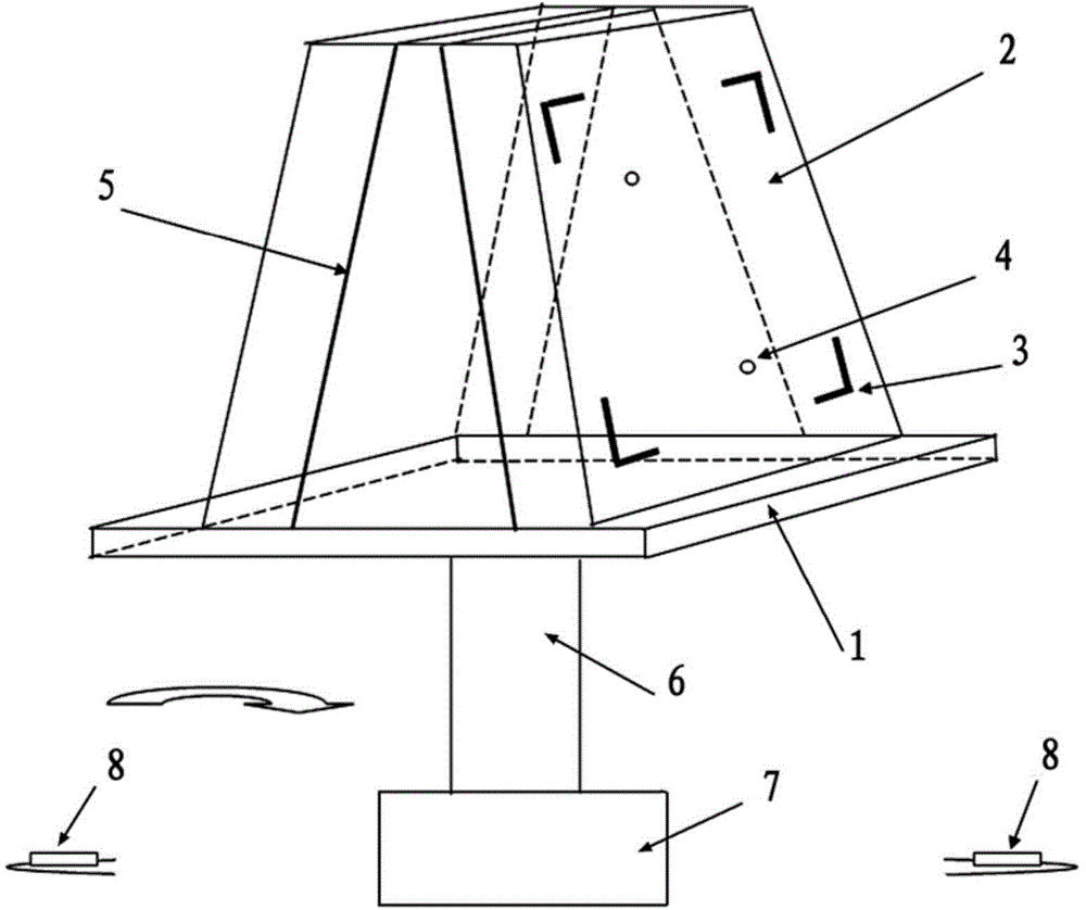
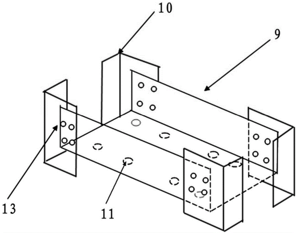
[0023] Such as figure 1 and image 3 As shown, a beam riveting jig provided by an embodiment of the present invention includes a rotatable platform 1 on which two riveting tools 2 are arranged, and the riveting tooling 2 includes a positioning notch 3 and a positioning The pin 4, the positioning notch 3 is arranged correspondingly to the beam connecting plate 10, the positioning pin 4 is arranged correspondingly to the positioning hole 11 on the beam 9, and the two riveting tools 2 are arranged symmetrically.
[0024] Usually, because the crossbeam connection plate 10 is "L" shape, therefore, the positioning gap 3 is also made into "L" shape, and the depth of the positionin...
PUM
 Abstract
Description
Claims
Application Information