Automatic build-up welding equipment for abrasion-resistant layer on inner wall of pipeline and automatic build-up welding method

An automatic surfacing and wear-resistant layer technology, applied in welding equipment, welding equipment, arc welding equipment, etc., can solve the problems of easy wear and tear of ordinary steel pipes, unguaranteed surfacing quality, and short service life, and achieve efficient automation. The effect of production, welding torch running smoothly and accurately, and simplified lifting mechanism

Inactive Publication Date: 2011-05-11
济南杰瑞复盛机电设备有限公司
View PDF9 Cites 37 Cited by
  • Summary
  • Abstract
  • Description
  • Claims
  • Application Information

AI Technical Summary

Problems solved by technology

[0002] In electric power, metallurgy, mining, building materials and other industries, when pipelines are used to transport ash, coal powder, mineral concentrate powder, concrete slurry and other materials, the inner wall of the pipeline not only bears severe wear, but sometimes also bears greater pressure. Under such working conditions, ordinary steel pipes are prone to wear and tear, and their service life is short.
In order to adapt to the above working conditions, a practical and effective method is to surfacing wear-resistant layers on the inner wall of ordinary carbon steel pipes, thereby producing a high-wear-resistant composite pipeline, which has a wide range of applications and a large demand. If manual welding is used, not only the production efficiency is low, the working conditions are poor, but also the quality of surfacing welding cannot be guaranteed. When the diameter of the pipe is relatively small, the welder cannot enter the pipe for surfacing operation at all.

Method used


Image

  • Automatic build-up welding equipment for abrasion-resistant layer on inner wall of pipeline and automatic build-up welding method
  • Automatic build-up welding equipment for abrasion-resistant layer on inner wall of pipeline and automatic build-up welding method

Examples


Embodiment Construction

[0048] The present invention will be described in further detail below in conjunction with the accompanying drawings and embodiments.

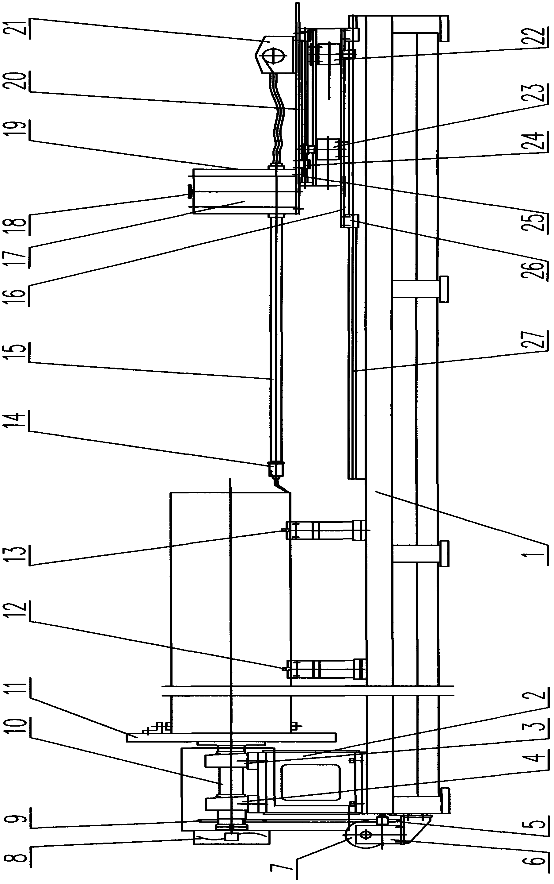
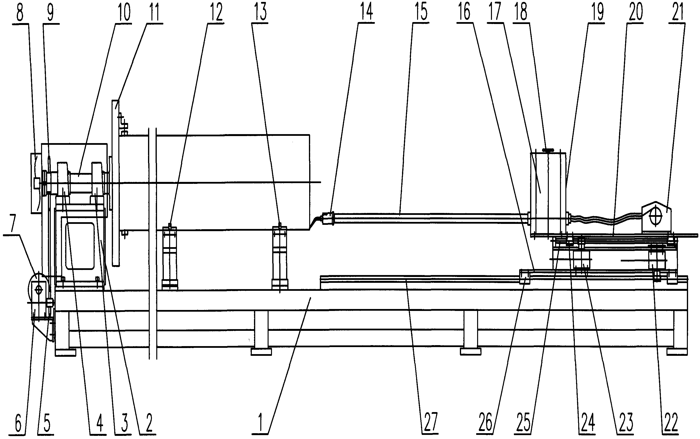
[0049] The automatic surfacing welding equipment for the wear-resistant layer on the inner wall of the pipeline includes a main engine, a DC gas shielded welding power supply, a storage tank containing shielding gas and a control box with a built-in automatic control device.

[0050] The main engine includes a machine base 1, which is a bar-shaped platform and is the installation basis of the whole main machine. One end of the machine base 1 is provided with a machine head 2, and the main shaft 10 is supported on the machine head 2 by two bearing supports 3 and 4. A support 6 is installed on the machine base 1 outside the machine head 2, and a stepping motor 7 is installed on the support 6. Driven sprocket 9 is arranged, drives main shaft 10 by chain, and the other end that is positioned at the inner side of machine head 2 of main shaft 10 is ...


PUM


Abstract

The invention discloses automatic build-up welding equipment for an abrasion-resistant layer on an inner wall of a pipeline and an automatic build-up welding method for realizing efficient automatic production of high abrasion-resistant composite conveying pipelines. The equipment comprises a host, a direct-current gas protective welding power supply, a protective gas storage tank and a control box with a built-in automatic control device; one end of a base is provided with a head, a main shaft, a chuck and an adjustable roller bracket; the other end of the base is provided with a welding gun running execution device, and the device comprises a driving and reversing platform, a swing platform, a welding gun lifting mechanism, a wire feeder and a welding gun; the front end of the welding gun is provided with a welding torch, and a welding wire and a protective gas conveying pipe are communicated to the front end of the welding gun; the anode of the welding power supply is connected with the welding torch, and the cathode of the welding power supply is connected with a workpiece; and the moving parts are driven by a step motor through the automatic control device. The operation process comprises early preparation, parameter setting, welding and reset stopping; and by setting control parameters, the execution parts run according to the set parameters to form build-up welding layers tightly arranged and uniformly distributed in a spiral motion locus.

Description

technical field [0001] The invention belongs to the field of welding technology, and in particular relates to an automatic surfacing welding equipment and an automatic surfacing welding method for a wear-resistant layer on the inner wall of a pipeline. Background technique [0002] In electric power, metallurgy, mining, building materials and other industries, when pipelines are used to transport ash, coal powder, mineral powder, concrete slurry and other materials, the inner wall of the pipeline not only bears severe wear, but sometimes also bears greater pressure. Under such working conditions, ordinary steel pipes are extremely easy to wear and tear, and have a short service life. In order to adapt to the above working conditions, a practical and effective method is to surfacing wear-resistant layers on the inner wall of ordinary carbon steel pipes, thereby producing a high-wear-resistant composite pipeline, which has a wide range of applications and a large demand. If m...

Claims


Application Information

Patent Timeline
Patent Type & Authority Applications(China)
IPC IPC(8): B23K9/04B23K9/16B23K9/095B23K9/32B23K37/047B23K37/02
Inventor 慕林伟陈春明
Owner 济南杰瑞复盛机电设备有限公司
Why Eureka
Try Eureka