Pneumatic tyre

A pneumatic tire, tire circumferential technology, applied to tire parts, tire tread/tread pattern, transportation and packaging, etc., can solve the problems of reduced tire rigidity, easy bending of stripes, and smaller stripes, so as to ensure rigidity Effect

Active Publication Date: 2015-03-18
TOYO TIRE & RUBBER CO LTD
View PDF8 Cites 24 Cited by
  • Summary
  • Abstract
  • Description
  • Claims
  • Application Information

AI Technical Summary

Problems solved by technology

However, if the width of the groove is large, the space between the stripes increases at the part with the larger width, and the stripe itself becomes smaller (thinner)
In this way, the stripes tend to bend under external force, so there is concern that the rigidity of the tire will decrease
Also in the case of increasing the formation density of the grooves, each stripe becomes smaller (thinner) due to the formation of grooves with small intervals, so there is a concern that the rigidity of the tire will decrease.

Method used


Image

  • Pneumatic tyre
  • Pneumatic tyre
  • Pneumatic tyre

Examples


Embodiment Construction

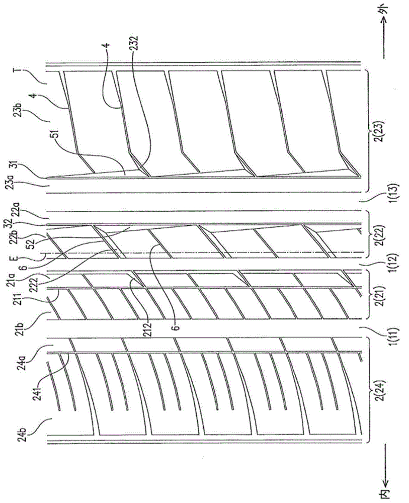
[0033] Next, the present invention will be described with reference to a pneumatic tire according to one embodiment. In addition, in the description of the following directions, regarding "inside and outside", when the tire is mounted on the vehicle, the side closer to the center in the width direction of the vehicle is defined as the inner side, and the side farther away is defined as the outer side. Additionally, the figure 1 , figure 2 , Figure 6 ~ Figure 9 The upper side of the tire is regarded as one side (or one end side) in the tire circumferential direction, and the lower side in the same figure is regarded as the other side (or the other end side) in the tire circumferential direction.

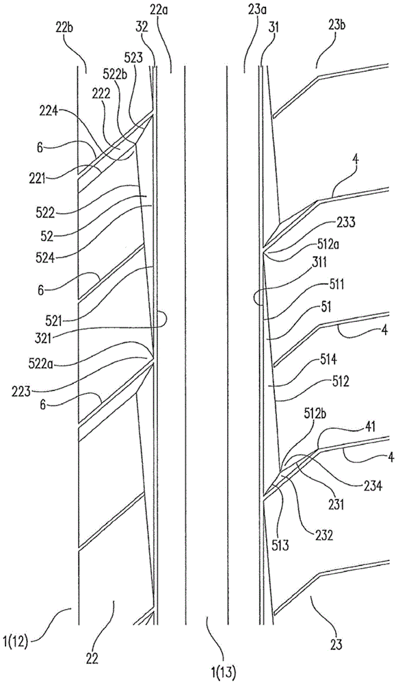
[0034] figure 1 It is a figure which shows the tread pattern of the tire of this embodiment, figure 2 yes figure 1 An enlarged view of the main part. The tread pattern of the tire is figure 1 The shown tire equator E is referenced and behaves asymmetrically across the width ...


PUM


Abstract

The invention provides a pneumatic tyre. The tread surface (T) is provided with at least one main groove (13) extending the circumferential direction of the tyre and at least one fine groove (31, 32) parallelly opposite to main groove (13), thin stripes (23a, 22a) which extend along the circumferential direction of the tyre and is located among the main groove (13) and the thin grooves (31, 32). Thick stripes (23b, 22b) are located at the sides opposite to the thin stripes (23a, 22a) in the width direction of the tyre of the thin grooves (31, 32) and provided with multiple notch portions (51, 52) adjacently connected to the thin grooves and arrayed along the circumferential direction of the tyre. The shapes of the multiple notches (51, 52) are characterized in that one end portion of each notch portion in the circumferential direction of the tyre has the large width in the width direction of the tyre and the other end portion of each notch portion has the smaller width in the width direction. The invention helps to ensure rigidity and obtain excellent heat dissipation performance.

Description

technical field [0001] The present invention relates to a pneumatic tire having ribs on a tread portion. Background technique [0002] Various tread patterns have been proposed for pneumatic tires (hereinafter referred to as tires) provided with ribs in the tread portion. For example, the tread pattern structure described in Patent Document 1. [0003] The tread pattern structure is as in Patent Document 1 figure 1 As shown, on one of the stripes located on the outer side of the vehicle outside the tire equator, a thin groove extending along the tire circumferential direction is formed (the document figure 1 The reference numeral "12" on the tire) and a plurality of inclined grooves extending from the thin groove to the equator side of the tire and leaving intervals in the circumferential direction of the tire (this document figure 1 reference number "16a") on the [0004] However, during the running of the vehicle, the tire deforms due to friction between the tire and t...

Claims


Application Information

Patent Timeline
Patent Type & Authority Applications(China)
IPC IPC(8): B60C11/13
Inventor 佐藤芳树
Owner TOYO TIRE & RUBBER CO LTD
Why Eureka
Try Eureka