Fuel supplying device

A fuel supply device and fuel technology, applied in the direction of liquid fuel feeder, charging system, engine components, etc., can solve the problems of unachievable cost reduction, pulsation, noise, unstable bottom shape, etc., and achieve cheap pressure regulation performance , Excellent effect of mute performance

Inactive Publication Date: 2015-03-18
MITSUBISHI ELECTRIC CORP
View PDF7 Cites 0 Cited by
  • Summary
  • Abstract
  • Description
  • Claims
  • Application Information

AI Technical Summary

Problems solved by technology

[0006] The conventional fuel supply device is constructed as described above. However, in the technique of Document 1, for example, since the pressure of the fuel reaching the inside of the fuel pipe of the engine depends on the dimensional accuracy of each part constituting the pressure regulator, there is no specific A mechanism that regulates pressure individually, so there is a problem of large fluctuations in fuel pressure
In addition, there is a p

Method used


Image

  • Fuel supplying device
  • Fuel supplying device
  • Fuel supplying device

Examples


Embodiment approach 1

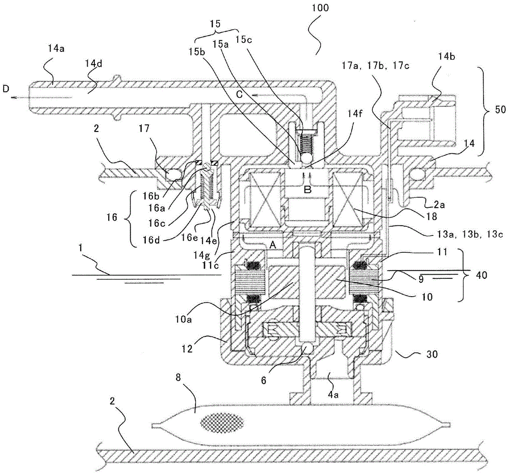
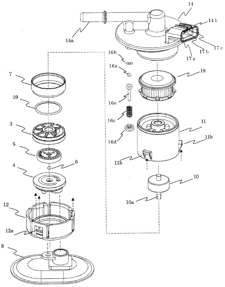
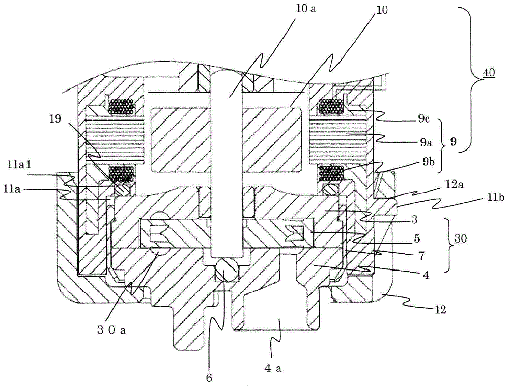
[0020] figure 1 It is a longitudinal sectional view of the fuel supply device in Embodiment 1 of the present invention, figure 2 Is an exploded perspective view of the fuel supply device in the first embodiment of the present invention, image 3 and 4 Yes figure 1 Enlarged view of the main parts of.

[0021] First, the structure of the fuel supply device 100 according to Embodiment 1 of the present invention will be described with reference to the drawings. in Figure 1 ~ Figure 4 Here, the fuel supply device 100 is hoisted on the opening 2a of the fuel tank 2 (shown partially broken) that stores the fuel 1 in a motorcycle, for example, and is composed of the following components: a pump part 30; a motor part 40, It serves as a driving source of the pump portion 30; and the flange portion 50 serves as an attachment member to be attached to the fuel tank 2.

[0022] The pump part 30 is constructed by accommodating the impeller 5 as a rotating part in the pump base 3 and the pump c...


PUM


Abstract

Provided is a fuel supplying device which can regulates pressure for each voltage regulator with a cheap structure and has excellent noise silencing performance. A fuel passage 14d and a return passage 80 are arranged in a flange portion 50, wherein the fuel passage 14d sends fuel to the outside of a fuel tank 2, and the return passage 80 returns fuel flowing by the fuel passage 14d back to the fuel tank 2. A support 16d is arranged on the voltage regulator in the return passage 80, and retains an elastic supported spring 16c on a fuel inlet of the return passage 80. The support can be retained on the flange portion 50 of the return passage 80 on a movable area E along the telescoping direction of the spring 16c.

Description

Technical field [0001] The present invention relates to a fuel supply device that is held in an opening of a fuel tank of a two-wheeled vehicle or the like and used to send fuel out of the fuel tank. Background technique [0002] A conventional fuel supply device has: a stator part formed by molding a resin material to cover an iron core formed of a magnet wound with a coil; and a rotor part rotatably arranged on the iron core If the coil is energized on the inner peripheral side, it is rotated by the magnetic field formed by the coil. In addition, it has a pump portion and a flange portion. The pump portion has: an impeller, which is fixed to the rotating shaft of the rotor; a pump housing, which rotatably houses the impeller; and a housing, which holds the pump housing on its outer periphery It is connected to the stator part, and the flange part holds the stator part, covers and fixes the opening provided in the container to the container, thereby fixing the fuel pump to the ...

Claims


Application Information

Patent Timeline
IPC IPC(8): F02M37/08
CPCF02M37/0052
Inventor 江口庆祐滨谷祐多郎
Owner MITSUBISHI ELECTRIC CORP
Why Eureka
Try Eureka