Automobile lamp module

A module and lamp technology, applied in the direction of headlights, vehicle parts, lighting and heating equipment, etc., can solve the problems of affecting appearance and lighting effect, uneven brightness of fisheye aperture, obvious distribution of bright spots, etc.

Inactive Publication Date: 2015-03-18
HONG FU JIN PRECISION IND (SHENZHEN) CO LTD +1
View PDF6 Cites 3 Cited by
  • Summary
  • Abstract
  • Description
  • Claims
  • Application Information

AI Technical Summary

Problems solved by technology

figure 1 Shown in is a structural schematic diagram of a fish-eye aperture used in a car light module in the prior art. It is provided with a light source at both ends of a circular light guide tube, and the light guide tube is made to emit light as a whole through light transmission. The heat dissipation of the light source must be considered, so the circular light guide ring has a large gap, which affects the appearance, and the part of the light guide far away from the light source has lower brightness than the part near the light source, that is, the brightness of the fisheye aperture will appear Uneven situation
and figure 2 Shown in is the lighting schematic diagram of the fish-eye aperture used by another car light module in the prior art. It directly arranges LEDs in a ring to form an aperture. Although the light utilization rate is extremely high, the LEDs directly face the light outlet to emit light. The distribution of bright cases is obvious, that is, the fisheye aperture will have uneven brightness, which will affect the overall appearance and lighting effect

Method used


Image

  • Automobile lamp module
  • Automobile lamp module
  • Automobile lamp module

Examples


Embodiment Construction

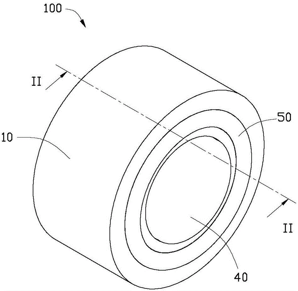
[0017] see image 3 and Figure 4 The vehicle lamp module 100 of the first embodiment of the present invention includes a lamp housing 10, a first accommodating cavity 12 formed by inwardly indenting the middle of the front end of the lamp housing 10, and a surrounding The annular second accommodating cavity 14 provided in the first accommodating cavity 12 , the first light source 20 accommodated in the first accommodating cavity 12 , and the second accommodating cavity 14 are accommodated The second light source 30, the first lampshade 40 fixed on the front end of the lamp housing 10 and covering the first light source 20 in the first accommodating cavity 12, and the front end of the lamp housing 10 and The second light source 30 covers the second lampshade 50 placed in the second accommodating cavity 14 .

[0018] The lamp housing 10 is integrally made of metal material or composite material. In this example, preferably, the lamp housing 10 is made of aluminum.

[0019] ...


PUM


Abstract

An automobile lamp module comprises a lamp shell, a first accommodating chamber, a second annular accommodating chamber, a first light source, a second light source, a first lampshade and a second annular lampshade; the middle of the front end of the lamp shell is concaved inward to form the first accommodating chamber; the front end of the lamp shell is concaved inward to form the second annular accommodating chamber which surrounds the first accommodating chamber; the first light source is accommodated in the first accommodating chamber; the second light source is accommodated in the second accommodating chamber; the first lampshade covers the first light source; the second annular lampshade covers the second light source; the inner wall surface of the second accommodating chamber is a continuous bending surface which comprises a plurality of reflection surfaces which are connected with each other in an intersected mode, wherein every reflection surface and each adjacent reflection surface are intersected in an inclined mode to form a certain angle and the second light source at least faces one of the reflection surfaces; the light emitted from the second light source is emitted out through the second lampshade after the continuous reflection between the reflection surfaces. Compared with the prior art, the light emitted from the second light source arranged in the automobile lamp module is uniformly scattered and accordingly the lighting effect of the automobile lamp module is improved and the light utilization rate is high.

Description

technical field [0001] The invention relates to a lamp module, in particular to a vehicle lamp module installed on a vehicle. Background technique [0002] The design of the vehicle light module firstly considers the lighting safety. In addition, many designs also focus on the appearance. The dazzling design can make the car a finishing touch and be favored by consumers. For example, installing a ring-shaped aperture around the headlights that play the main role of lighting can make the appearance of the car look like two eyes, commonly known as fish-eye apertures, which can make the appearance of the lamp module better, and at the same time play an auxiliary lighting effect . [0003] At present, the light source of fisheye aperture mainly adopts cold-cathode fluorescent lamp (CCFL) and light-emitting diode (LED). Traditional CCFL has the advantages of low cost and uniform brightness, but at the same time has the disadvantages of easy to cause environmental pollution and s...

Claims


Application Information

Patent Timeline
Patent Type & Authority Applications(China)
IPC IPC(8): F21S8/10F21V13/04F21Y101/02
CPCF21S41/32F21S41/18
Inventor 陈柏洲
Owner HONG FU JIN PRECISION IND (SHENZHEN) CO LTD
Why Eureka
Try Eureka