Image formation device

An image and equipment technology, applied in the field of image forming equipment, can solve problems such as photosensitive drum damage, achieve the effect of suppressing peripheral surface damage and realizing miniaturization

Active Publication Date: 2015-03-18
BROTHER KOGYO KK
View PDF7 Cites 0 Cited by
  • Summary
  • Abstract
  • Description
  • Claims
  • Application Information

AI Technical Summary

Problems solved by technology

[0005] However, in the printer described in Patent Document 1, since the head end of the cleaning sheet is always in contact with the peripheral surface of the photosensitive drum, the peripheral surface of the photosensitive drum may be damaged due to repeated image forming operations.

Method used


Image

  • Image formation device
  • Image formation device
  • Image formation device

Examples


Embodiment Construction

[0052] 1. Printer

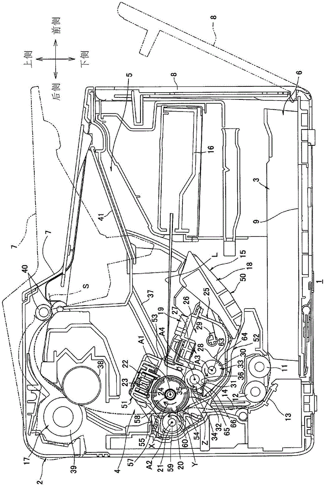
[0053] Such as figure 1 As shown, a printer 1 as an example of an image forming apparatus has a main body casing 2 in a substantially box shape.

[0054] The printer 1 has, inside a main body casing 2 , a paper supply unit 3 for supplying paper S as an example of a recording medium, and an image forming unit 4 for forming an image on the supplied paper S.

[0055] In the following description, when referring to directions, the printer 1 is placed horizontally as a reference, and figure 1 The right side of the paper is the front side, with figure 1 The left side of the paper is the rear side. Based on the left and right when viewing the printer 1 from the front side, takefigure 1 The near front side of the paper is the left side, and the deep side of the paper is the right side.

[0056] That is, each of the front-rear direction and the left-right direction is a horizontal direction, and the up-down direction is a vertical direction.

[0057] (1) Body s...


PUM


Abstract

Provided is an image formation device capable of suppressing damage to the peripheral surface of a photosensitive drum, and definitively removing and collecting an adhering substance which adheres to the peripheral surface of the photosensitive drum. A printer (1) equipped with a photosensitive drum (20) for rotating around a center-axis line (A1), and a developing roller (34) for rotating around a center-axis line (A4), wherein the developing roller (34) is positioned in a manner such that the center-axis line (A4) is below (bottom-side in vertical direction) the center-axis line (A1). Consequently, the printer (1) is configured in a manner such that it is possible to supply toner to the photosensitive drum (20), and recover the adhering substance which adheres to the peripheral surface of the photosensitive drum (20).

Description

technical field [0001] The present invention relates to an image forming apparatus employing electrophotography. Background technique [0002] As an electrophotographic image forming apparatus, as described in Patent Document 1, a printer is known, which has: a photoreceptor drum for forming an electrostatic latent image; a developing roller for supplying an electrostatic latent image; and a cleaning blade for scraping off, from the peripheral surface of the photoreceptor drum, adhering matter (such as toner) adhering to the peripheral surface of the photoreceptor drum during image formation. [0003] In the above-mentioned printer, by bringing the head end portion of the cleaning sheet into contact with the peripheral surface of the photosensitive drum, the attached matter adhering to the peripheral surface of the photosensitive drum is scraped off. [0004] Patent Document 1: Japanese Patent Application Laid-Open No. 8-194417 [0005] However, in the printer described in...

Claims


Application Information

Patent Timeline
Patent Type & Authority Applications(China)
IPC IPC(8): G03G15/00G03G15/02G03G15/08G03G15/16
CPCG03G21/1814G03G21/0064G03G2221/0026
Inventor 半田弘司尾藤猛森启城
Owner BROTHER KOGYO KK
Why Eureka
Try Eureka