Circular forming knife rest type milling assembly

A forming knife and frame type technology, which is applied to milling cutting inserts, milling cutters, milling machine equipment, etc., can solve the problems of complicated inspection and debugging work, heavy disassembly, replacement, and complicated design of forming equipment, etc., and achieves blade maintenance. The effect of convenience, easy handling, and strong expansion of milling path processing

Active Publication Date: 2015-03-25
CRCC HIGH TECH EQUIP CORP LTD
View PDF7 Cites 6 Cited by
  • Summary
  • Abstract
  • Description
  • Claims
  • Application Information

AI Technical Summary

Problems solved by technology

The above-mentioned disassembly and replacement workload is large, and when the outer dimension of the disc base is large, the instruments required for re-testing and adjusting the position of the cutting blade after replacement are also relatively large, and the detection and debugging work is complicated; in addition, the replacement of the milling disc takes up a lot Large space, especially for online forming equipment, the replacement, detection and adjustment of worn blades will lead to complex design of forming equipment, the size of the equipment used for tool storage and detection space is too large, and the equipment cost increases.

Method used


Image

  • Circular forming knife rest type milling assembly
  • Circular forming knife rest type milling assembly
  • Circular forming knife rest type milling assembly

Examples


Embodiment 1

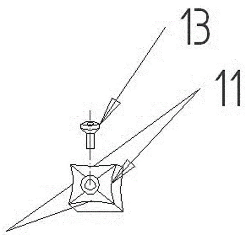
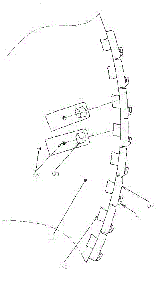
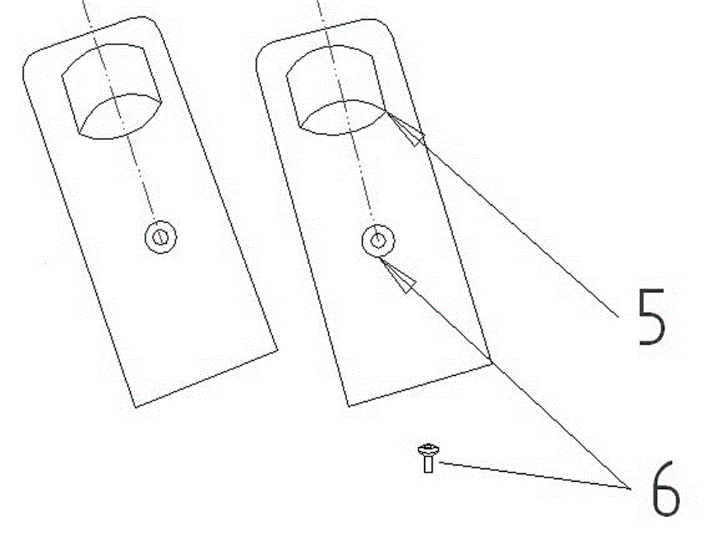
[0067] Embodiment one: figure 1 It is a structural schematic diagram of a preferred embodiment in which the tool post milling assembly of the peripheral forming tool post milling assembly of the present invention cooperates with the peripheral forming cutter head base, figure 2 for figure 1 A schematic structural view of a preferred embodiment of the tool holder type milling assembly of the illustrated embodiment, image 3 for figure 2 A schematic structural view of a preferred embodiment of the blade A of the illustrated embodiment, Figure 4 for figure 2 A schematic structural view of a preferred embodiment of the blade B of the illustrated embodiment, Figure 5 for figure 1 In the shown embodiment, it is a schematic diagram of the assembly between the tool rest milling assembly and the circumferentially shaped cutter base through bolts and stoppers.

[0068] In this embodiment, a circumferential forming cutter head type milling assembly includes a circumferential f...

Embodiment 2

[0095] Embodiment 2: A milling assembly with a circumferentially shaped tool post, which is the same as Embodiment 1, except that the blade B has four arc cutting edges.

Embodiment 3

[0096] Embodiment 3: A circumferentially shaped tool holder type milling assembly, which is the same as Embodiment 1, except that three rows of cutting blades are arranged on the tool holder type milling assembly.


PUM


Abstract

The invention discloses a circular forming knife rest type milling assembly which comprises a circular forming cutter head base body, wherein a knife rest type milling assembly is arranged on the edge of the base body; at least two columns of cutting blades are arranged on the knife rest type milling assembly; and the two columns of cutting blades are arranged in a staggered mode in a direction perpendicular to the circular cutting direction. According to the knife rest type milling assembly disclosed by the invention, blank parts of various materials can be subjected to circular forming milling, the knife rest type milling assembly is particularly applied to milling the railway rail head profile and has the advantages of convenience in blade maintenance, convenience in knife rest storage, high tool track machining expandability and the like, and the development of the circular forming, particularly the development of the circular forming technology of the railway rail head profile and the tool application, is promoted.

Description

technical field [0001] The invention relates to a circumferential forming tool holder type milling assembly, which realizes the forming process of blanks of various materials, in particular to a milling assembly suitable for circumferential milling to form railway rails with different rail profiles. Background technique [0002] As an infinitely long beam supported on a continuous elastic foundation, the rail mainly bears the concentrated vertical load from the locomotive and produces a certain bending moment on its section. The rail includes the rail head, rail waist and rail bottom. As the operation time increases, various diseases will occur at the contact point with the vehicle tread, such as corrugation, flash, uneven joints, etc., which will affect the comfort of the running train and accelerate the loss of the rail. Therefore, it is necessary to repair the rail On-line reshaping of the rail profile achieves the purpose of prolonging the service life of the rail, impro...

Claims


Application Information

Patent Timeline
Patent Type & Authority Applications(China)
IPC IPC(8): B23C5/20B23C5/22
CPCB23C3/005B23C5/08B23C5/2226B23C2200/04B23C2200/0433B23C2200/083B23C2200/32B23C2210/207
Inventor 蔡昌胜方健康胡斌熊泽民李海昆韩双平
Owner CRCC HIGH TECH EQUIP CORP LTD
Why Eureka
Try Eureka