
Headstock device of high-speed internal grinding machine

An internal cylindrical grinding machine and headstock technology, which is applied to grinding machines, grinding workpiece supports, machine tools designed for grinding workpiece rotating surfaces, etc., can solve problems affecting grinding accuracy, insufficient processing speed, grinding efficiency and grinding efficiency. problems such as adverse effects on accuracy, to achieve the effects of a large range of machinable angles, ingenious and reasonable structural design, and improved machining accuracy and efficiency

Inactive Publication Date: 2015-03-25
WUXI DA ROMA CNC MACHINE MFG
View PDF10 Cites 5 Cited by
  • Summary
  • Abstract
  • Description
  • Claims
  • Application Information

AI Technical Summary

Problems solved by technology

However, the existing grinding machines have the disadvantage that the inner circle angle of the workpiece cannot be adjusted or the adjustment range is very small. For the occasions where the inner circle angle of the workpiece is required to be processed, multiple clamping is required, and multiple clamping will affect the grinding. precision
Moreover, the existing internal grinding machine still has the problem that the processing speed is not high enough, which also has an adverse effect on the grinding efficiency and grinding accuracy.

Method used


Image

  • Headstock device of high-speed internal grinding machine
  • Headstock device of high-speed internal grinding machine

Examples


Embodiment Construction

[0016] The present invention will be further described below in conjunction with specific drawings and embodiments.

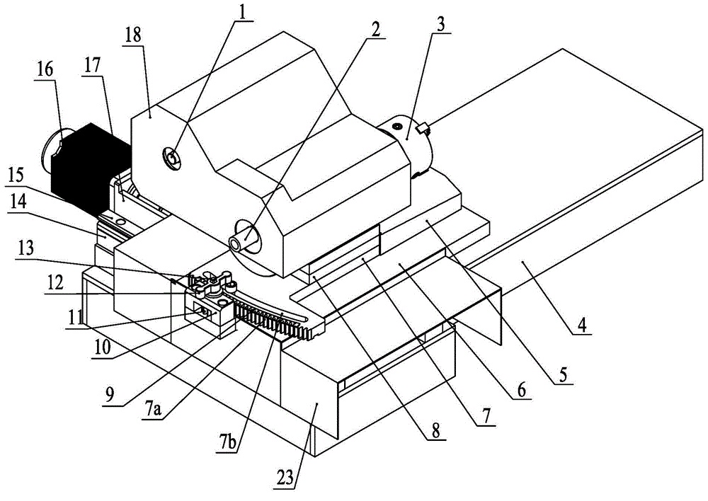
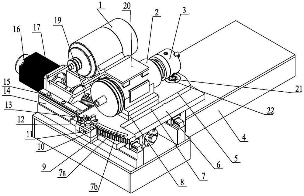
[0017] As shown in the figure: the headstock device of the high-speed internal grinding machine in the embodiment is installed on the workbench base 4, and the headstock device is mainly composed of a longitudinal line rail seat 14, a longitudinal linear slide rail 15, a plane rotary table of the headstock device, Longitudinal feed driving mechanism, spindle head 2, spindle motor 1, motor mounting frame 20 and chuck 3 are composed of two longitudinal line rail seats 14 arranged in parallel longitudinally and fixedly installed on the left end of the workbench base 4, two longitudinal line rail seats A longitudinal linear slide rail 15 is respectively installed on the top of the seat 14, and the plane rotary workbench of the headstock device is placed on the two longitudinal linear slide rails 15, and the slide on the plane rotary workbench of the headstock device...


PUM


Abstract

The invention relates to a headstock device of a high-speed internal grinding machine. Two longitudinal linear rail chairs are longitudinally arranged in parallel and fixedly installed at the left end of a worktable base. The tops of the two longitudinal linear rail chairs are each provided with a longitudinal linear sliding rail. A headstock device plane rotating worktable is placed on the two longitudinal linear sliding rails and fixedly connected with sliding blocks on the longitudinal linear sliding rails. The headstock device plane rotating worktable is driven by a longitudinal feeding driving mechanism to horizontally and longitudinally move. A spindle head is horizontally and transversely arranged and installed on the headstock device plane rotating worktable. A spindle motor is fixedly installed on the spindle head through a motor mounting rack. The power output end of the spindle motor is connected with the power input end of the spindle head. The output end of the spindle head is provided with a chuck rightwards, wherein the chuck is used for clamping a workpiece. The headstock device can conduct longitudinal feeding and can achieve plane rotating adjustment, the machining angle range of the internal circle of the workpiece is large, and the machining precision and efficiency can be greatly improved.

Description

technical field [0001] The invention relates to an internal grinding machine, specifically a headstock device of a high-speed internal grinding machine, and belongs to the technical field of mechanical processing equipment. Background technique [0002] The internal grinding machine is mainly used for grinding the surface of the inner hole and the end surface of the cylindrical, conical or other shapes. Existing internal grinding machine mainly is made up of lathe bed, the headstock device that is arranged on lathe bed and grinding device. The head frame device is used for the head frame to install and hold the workpiece and drive the workpiece to rotate. The grinding device is equipped with a grinding wheel, which is used for grinding the workpiece. [0003] The degree of automation of internal grinding machines commonly used in some enterprises is not high, and the grinding size is usually controlled by workers' measurement. Only suitable for single piece and small batch...

Claims


Application Information

Patent Timeline
Patent Type & Authority Applications(China)
IPC IPC(8): B24B5/01B24B5/35B24B41/06
CPCB24B5/01B24B5/35B24B41/062
Inventor 吕国栋包为能
Owner WUXI DA ROMA CNC MACHINE MFG
Learn More