Telescopic G-shaped clamp

A clamp body and movable clamp technology, applied in the direction of clamps, manufacturing tools, etc., can solve the problems of limited adjustable range, non-adjustable size, and inability to use G-shaped clamps.

Inactive Publication Date: 2015-03-25
CHANGZHOU HOUXIAO YUHENG CURTAIN WALL
View PDF0 Cites 4 Cited by
  • Summary
  • Abstract
  • Description
  • Claims
  • Application Information

AI Technical Summary

Problems solved by technology

The G-shaped clamps currently used include clamp body, screw rod, and cross bar. The clamp body is generally a fixed structure, and its size cannot be adjusted, which limits the scope of use of the G-shaped clamp. For workpieces that exceed the scope of use of the...

Method used


Image

  • Telescopic G-shaped clamp
  • Telescopic G-shaped clamp

Examples


Embodiment 1

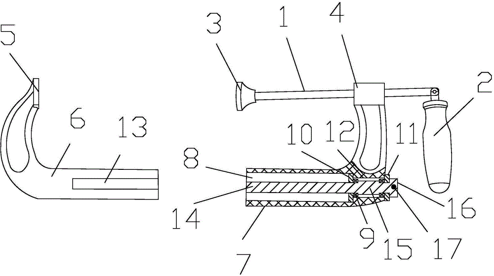
[0016] see figure 1 , a retractable G-shaped clip, including a G-shaped clip body, a screw rod 1, a handle 2, and a joint head 3. The clip body is provided with a clamping end 5 and a mounting end 4, and the mounting end is provided with a threaded hole. The screw rod and the threaded The holes are threaded, the handle and the movable head are respectively arranged at the two ends of the screw rod, the movable head is arranged opposite to the clamping end, the clamp body includes a movable clip and a fixed clip, and the movable clip and the fixed clip both include a horizontal section and a Vertical section, the movable clip vertical section 7 is provided with the slotted hole 8 that can accommodate the fixed clip vertical section 6, and the fixed clip vertical section is movably sleeved in the slotted hole of the movable clip vertical section, and the movable clip is vertically The connection between the segment and the vertical segment of the fixing clip is realized through ...

Embodiment 2

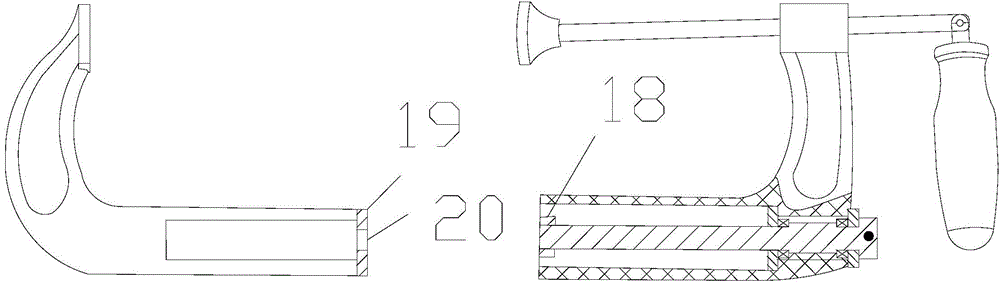
[0022] On the basis of Embodiment 1, the end of the threaded section is provided with a cylindrical block 18 with an external thread and a larger diameter than the threaded section, and the cylindrical block is screwed with the blind hole; the end of the blind hole is provided with End cap B19, the center of the end cap B is provided with a threaded hole 20 equal in diameter to the threaded section, the threaded section is threaded into the threaded hole, and the end cap B is fixedly connected to the end of the vertical section of the fixing frame by bolts.


PUM


Abstract

The invention relates to a telescopic G-shaped clamp which comprises a G-shaped clamp body, a screw rod, a handle and a moving head. The clamping body is provided with a clamping end and a mounting end. The mounting end is provided with a thread hole. The screw rod is in thread connection with the thread hole. The handle and the moving head are arranged at the two ends of the screw rod respectively. The moving head is arranged right opposite to the clamping end. The clamping body comprises a moving clamp and a fixed clamp. The moving clamp and the fixed clamp both comprise horizontal sections and vertical sections. The vertical section of the moving clamp is provided with a groove hole in which the vertical section of the fixed clamp can be contained. The vertical section of the fixed clamp is movably arranged in the groove hole of the vertical section of the moving clamp in a sleeved mode. The vertical section of the moving clamp and the vertical section of the fixed clamp are connected though a connecting mechanism. According to the scheme, the fixed clamp and the moving clamp are arranged, telescopic adjusting of the clamp body is achieved, and the clamping range of the G-shaped clamp is increased.

Description

technical field [0001] The invention relates to a clamp, in particular to a retractable G-shaped clamp. Background technique [0002] G-clip is a G-shaped hardware tool used to clamp various shapes of workpieces, modules, etc. for fixing. The G-shaped clamps currently used include clamp body, screw rod, and cross bar. The clamp body is generally a fixed structure, and its size cannot be adjusted, which limits the scope of use of the G-shaped clamp. For workpieces that exceed the scope of use of the G-shaped clamp, it cannot Use the G folder. In addition, although there are also adjustable G-shaped clips with clip bodies connected by a horizontal ruler in the market, the stability of the G-shaped clips with this structure is poor, and the adjustable range is still limited. Contents of the invention [0003] In view of the above problems, the object of the present invention is to provide a retractable G-word folder. [0004] Realize the technical scheme of the present inv...

Claims


Application Information

Patent Timeline
IPC IPC(8): B25B5/02B25B5/16
CPCB25B5/101B25B5/02B25B5/16
Inventor 孔立峰
Owner CHANGZHOU HOUXIAO YUHENG CURTAIN WALL
Why Eureka
Try Eureka