U-shaped workpiece conveying device

A technology for conveying devices and workpieces, applied in the direction of conveyor objects, transportation and packaging, etc., can solve problems such as easy congestion, easy failures, and affecting efficiency

Inactive Publication Date: 2015-03-25
CHANGZHOU GALAXY INNOVATION MAGNETOELECTRICITY
View PDF0 Cites 3 Cited by
  • Summary
  • Abstract
  • Description
  • Claims
  • Application Information

AI Technical Summary

Problems solved by technology

[0002] When the existing conveying device is conveying materials, due to the large number of workpieces in the hopper, the materials cannot be conveyed in an orderly manner, and congestion is prone to occur,

Method used


Image

  • U-shaped workpiece conveying device

Examples


Embodiment Construction

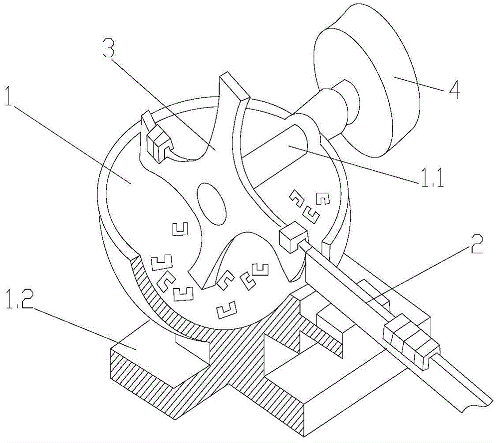
[0013] Such as figure 1 A U-shaped workpiece conveying device shown includes a hopper 1, a slideway 2, and a pick-up paddle 3. The pick-up paddle 3 with four blades is vertically arranged in the hopper 1, and the pick-up paddle 3 is arranged There is a rotating shaft 1.1 extending to the outside of the hopper. The rotating shaft 1.1 is connected to the motor 4 arranged on the side of the hopper 1. The motor 4 is provided with a reducer for easy speed control. Extending to the outside of the hopper 1, the slideway 2 and the pick-up paddle 3 are on the same straight line, the edge of the pick-up paddle 3 is tangent to the front end of the slideway 2, and the blade of the pick-up paddle 3 is an arc shape transition, the blade edge end surface is also arc-shaped, and the bottom of the hopper 1 is provided with a fixed base 1.2.

[0014] The above is only a preferred embodiment of the present invention, and does not limit the present invention in any form. Any simple modification ...


PUM


Abstract

The invention relates to the technical field of conveying devices, in particular to a U-shaped workpiece conveying device. The U-shaped workpiece conveying device comprises a hopper, a slideway and a picking paddle, wherein the picking paddle is provided with a plurality of vanes, vertically arranged in the hopper and provided with a rotary shaft extending to the outside of the hopper, the rotary shaft is connected with a driving rotation device, the front end of the slideway extends into the hopper in an upward inclination mode, the rear portion of the slideway extends to the outside of the hopper, the slideway and the picking paddle are on the same straight line, the edge of the picking paddle is tangent with the front end of the slideway, the vanes of the picking paddle are in arc transition, and the end surface of the edge of each vane is also arc. The U-shaped workpiece conveying device is exquisite and simple in structure, not prone to faults and high in efficiency.

Description

technical field [0001] The invention relates to the technical field of conveying devices, in particular to a U-shaped workpiece conveying device. Background technique [0002] When the existing conveying device is conveying materials, due to the large number of workpieces in the hopper, the materials cannot be conveyed in an orderly manner, and congestion is prone to occur, resulting in poor material conveying in the hopper and affecting efficiency. The addition of a mechanism to prevent workpiece congestion will undoubtedly make the overall structure Complicated and prone to failure. Contents of the invention [0003] The technical problem to be solved by the present invention is to provide a U-shaped workpiece conveying device for the above defects, which has an exquisite and simple structure, is not prone to failure, and has high efficiency. [0004] The technical scheme that the present invention solves its technical problem adopts is as follows: [0005] A U-shaped ...

Claims


Application Information

Patent Timeline
IPC IPC(8): B65G47/14
Inventor 范耀明张灯
Owner CHANGZHOU GALAXY INNOVATION MAGNETOELECTRICITY
Why Eureka
Try Eureka