Steel bridge deck laying structure

A steel bridge deck and pavement technology, which is applied to bridges, bridge parts, bridge materials, etc., to achieve the effects of light weight, high strength and strong adhesion

Inactive Publication Date: 2015-03-25
ANHUI TRANSPORTATION INVESTMENT GRP
View PDF5 Cites 5 Cited by
  • Summary
  • Abstract
  • Description
  • Claims
  • Application Information

AI Technical Summary

Problems solved by technology

[0005] In order to solve the deficiencies in the existing steel bridge deck pavement structure of asphalt mixture, the present invention provides a steel bridge deck pavement structure

Method used


Image

  • Steel bridge deck laying structure

Examples


Embodiment Construction

[0020] The present invention will be further described through the embodiments below in conjunction with the accompanying drawings.

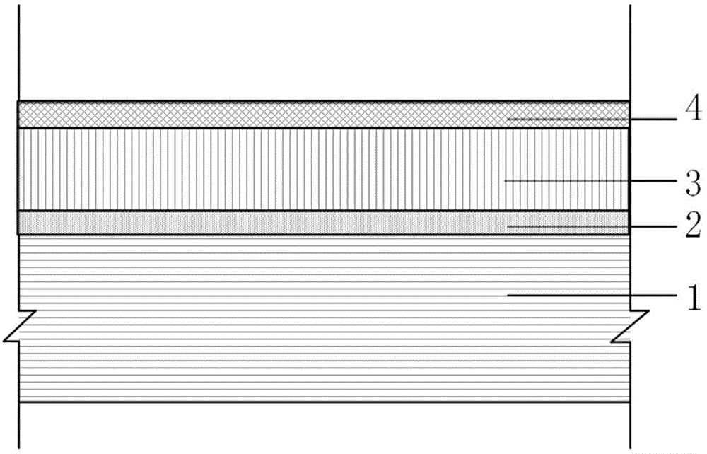
[0021] see figure 1 , a steel bridge deck pavement structure, comprising a steel bridge deck 1, an elastic crack-resistant layer 3 is laid on the steel bridge deck 1 through a bonding layer 2, and a wear layer 4 is arranged on the elastic crack-resistant layer 3.

[0022] The material of the bonding layer 2 is a two-component polyurethane modified resin special adhesive, and the thickness of the bonding layer 2 is 1-1.5mm; the material of the elastic anti-cracking layer 3 is a two-component high thixotropic pure elastic polyurethane modified The thickness of the elastic anti-cracking layer 3 is 6-7 mm; the material of the wearing layer 4 is two-component polyurethane modified polymer gravel, and the thickness of the wearing layer 4 is 3-5 mm.

[0023] The materials of the adhesive layer 2, the elastic anti-crack layer 3 and the wear layer 4 are...


PUM

PropertyMeasurementUnit
thicknessaaaaaaaaaa
thicknessaaaaaaaaaa
thicknessaaaaaaaaaa

Abstract

A steel bridge deck laying structure comprises a bonding layer, an elastic anti-cracking layer and an abrasion layer. The elastic anti-cracking layer is laid on the upper surface of the bonding layer, and the abrasion layer is tightly attached to the upper surface of the elastic anti-cracking layer. The bonding layer is made from bi-component polyurethane modified special resin glue, the elastic anti-cracking layer is made from bi-component high-thixotropic purely elastic polyurethane modified polymer gravels, and the abrasion layer is made from bi-component polyurethane modified polymer gravels.

Description

technical field [0001] The invention belongs to the technical field of bridge deck pavement structures, in particular to a steel bridge deck pavement structure. Background technique [0002] At present, there are three types of steel bridge deck pavement schemes in the world: (1) Asphalt mixture: Pavement made of asphalt mastic macadam (SMA), cast asphalt concrete (GA) and epoxy asphalt concrete (EA) ; (2) Cement concrete: paved by high performance concrete (HPC) and polymer modified concrete (LMC); (3) Paved with high molecular polymers. [0003] The mechanical characteristics of the steel bridge deck pavement are: (1) the presence of longitudinal stiffeners and diaphragms makes the top of the pavement under the load to locally bear a relatively large negative bending moment; (2) the long-span steel box girder The deformation, displacement, vibration, and torsion of the bridge itself are large; (3) Seasonal temperature changes will have a serious impact on the steel box gi...

Claims


Application Information

Patent Timeline
Patent Type & Authority Applications(China)
IPC IPC(8): E01D19/12
CPCE01D19/125E01D2101/40
Inventor 杨晓光胡可郑建中左敦礼张尤平桂永全赵可肖魏星黄涛李品赵加信熊亮连俊峰汪家勇孙海鹏陈蓓蓓张孝虹韩磊
Owner ANHUI TRANSPORTATION INVESTMENT GRP
Why Eureka
Try Eureka