Blowing fan

A blower fan and fan wheel technology, which is applied to components of pumping devices for elastic fluids, non-variable pumps, machines/engines, etc., can solve problems such as easy collision with fan frames, and prevent damage to fan wheels, Effects of avoiding noise and preventing collision situations

Active Publication Date: 2015-03-25
SUNON ELECTRONICS (BEIHAI) CO LTD
View PDF7 Cites 9 Cited by
  • Summary
  • Abstract
  • Description
  • Claims
  • Application Information

AI Technical Summary

Problems solved by technology

[0006] The main purpose of the present invention is to provide a blower fan, which is used to effectively improve the problem that the "fan wheel with a chassis" of the above blower fan is easy to collide with the fan frame during rotation.

Method used


Image

  • Blowing fan
  • Blowing fan
  • Blowing fan

Examples


Embodiment Construction

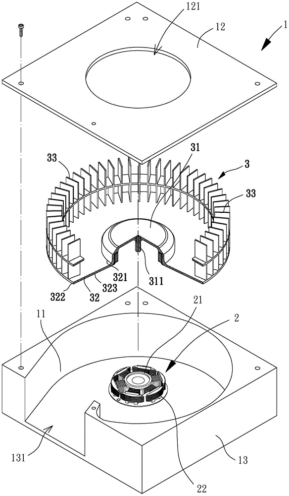
[0038] Please refer to image 3 and Figure 4 As shown, the blower fan of the preferred embodiment of the present invention at least includes a fan frame 1 , a stator set 2 and a fan wheel 3 . The fan frame 1 is a frame structure capable of axially introducing airflow and radially exporting airflow; the stator group 2 is combined inside the fan frame 1; the fan wheel 3 is rotatably combined with the stator group 2, so that Group 2 drives the fan wheel 3 to rotate.

[0039] The above-mentioned fan frame 1 can be a hollow frame structure capable of accommodating the above-mentioned stator group 2 and the above-mentioned fan wheel 3 and allowing air flow to be introduced in the axial direction and exported in the radial direction. The hollow frame structure can be of various geometric shapes. The structural design of the shape, such as polygonal, circular or elliptical, etc.; in this preferred embodiment, the fan frame 1 is disclosed as a square frame structure.

[0040] The a...


PUM


Abstract

The invention relates to a blowing fan which is used for solving the problem that when a fan wheel of an existing blowing fan rotates, a chassis of the blowing fan is easily collided with a fan frame. The blowing fan comprises a fan frame, a stator set and a fan wheel. The fan frame comprises a base plate part and a cover plate part, a lateral wall part is arranged between the base plate part and the cover plate part, an air inlet is formed in the cover plate part, and an air outlet is formed in the lateral wall part. The stator set is arranged inside the fan frame; the fan wheel is arranged between the base plate part and the cover plate part of the fan frame, combined with the stator set, and provided with a wheel hub, the peripheral face of the wheel hub extends in the radial direction to form the chassis, and a plurality of blades are arranged on the surface of at least one side of the chassis. The chassis of the fan wheel extends in the radial direction from the wheel hub to the lateral wall part, and is inclined in the direction of the cover plate part.

Description

technical field [0001] The invention relates to a blower fan, in particular to a blower fan which can prevent the fan wheel from colliding with the fan frame during rotation. Background technique [0002] Please refer to figure 1 As shown, the conventional blower fan 8 roughly includes a fan frame 81 , a stator set 82 and a fan wheel 83 . The fan frame 81 is provided with an axial air inlet 811 and a radial air outlet 812; the stator group 82 is arranged inside the fan frame 81; the fan wheel 83 is rotatably combined with the stator group 82; wherein the fan wheel 83 has A hub 831 , a chassis 832 extends radially from the bottom end of the outer peripheral surface of the hub 831 , and the chassis 832 is provided with several blades 833 . Thereby, when the stator group 82 drives the fan wheel 83 to rotate, the fan wheel 83 can introduce airflow from the axial air inlet 811, and cooperate with the guiding function of the chassis 832 to let the airflow out from the radial dir...

Claims


Application Information

Patent Timeline
Patent Type & Authority Applications(China)
IPC IPC(8): F04D29/28
CPCF04D29/281
Inventor 洪银树
Owner SUNON ELECTRONICS (BEIHAI) CO LTD
Why Eureka
Try Eureka