a rotary clutch

A clutch and piston technology, applied in the field of hydromechanical transmission, can solve the problems of increasing the difficulty of installation structure design, increasing the overall length and size of the auxiliary gearbox, etc., to reduce the difficulty of structural design and layout structure design, compact structure, and reduce the number of shafts. To the effect of the length dimension

Active Publication Date: 2017-07-25
贵州凯星液力传动机械有限公司
View PDF7 Cites 0 Cited by
  • Summary
  • Abstract
  • Description
  • Claims
  • Application Information

AI Technical Summary

Problems solved by technology

[0002] In the previous design of various hydraulic mechanical transmission rotary clutches, a rotary clutch generally has only one speed ratio. In the traditional multi-gear, multi-speed ratio design, only two or more rotary clutches Connecting in series can meet the design requirements of gear position and speed ratio, which not only increases the overall length of the auxiliary gearbox, but also increases the design difficulty of its installation structure in order to ensure that the rotating clutches do not interfere during operation.

Method used


Image

  • a rotary clutch
  • a rotary clutch
  • a rotary clutch

Examples


Embodiment 1

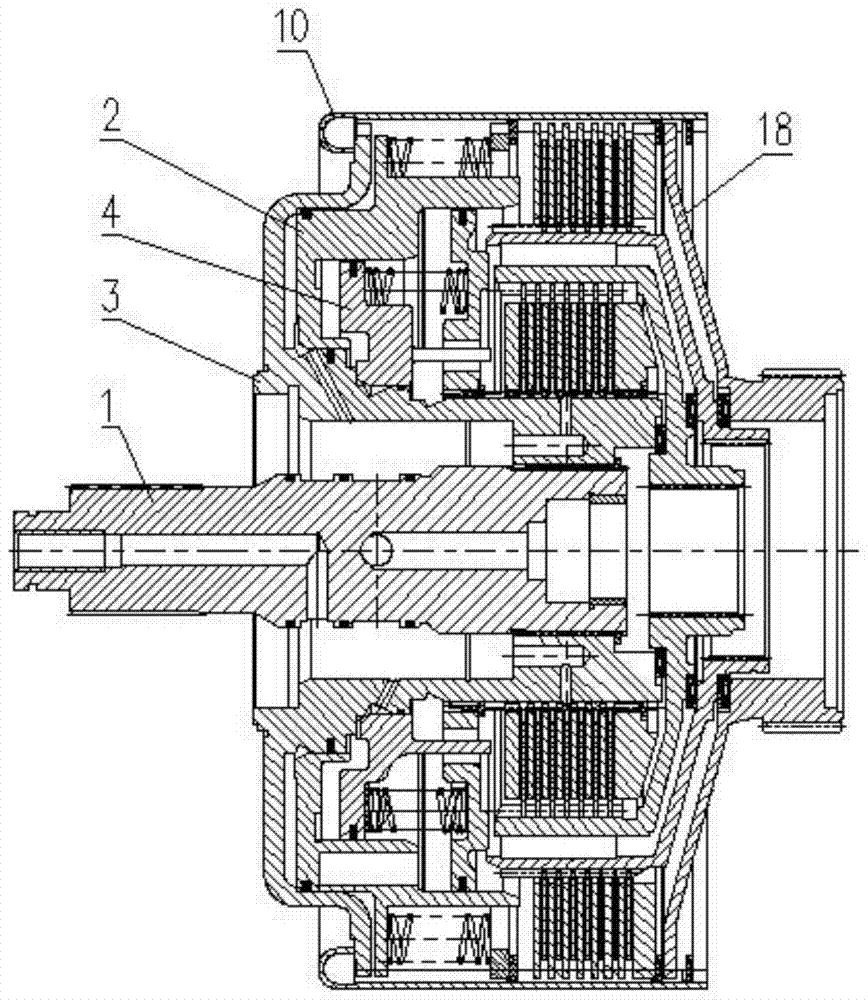
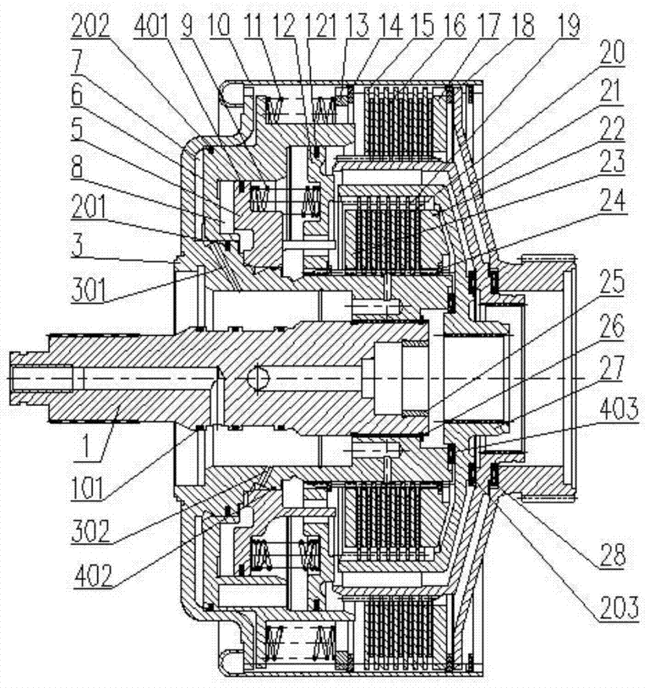
[0031] Embodiment one: if Figure 4 As shown, there are two radial small holes on the driving hub 3, which are used for the lubricating oil of the C2 clutch 4 and the sliding bearing 25 to enter the oil, and the external teeth on the large outer edge of the driving hub 3 and the internal teeth of the ring gear 10 Cooperate; one end of the C1 piston return spring 11 is against the end face of the C1 piston 6, and the other end is against the end face of the C1 piston return spring baffle plate 13; there is a C1 outer friction plates 15 and C1 inner friction plates 16 are staggered with 7 pieces each, the outer teeth of C1 outer friction plates 15 are combined with the inner teeth of inner ring gear 10, and the inner splines of C1 inner friction plates 16 are driven by C1 The external spline fit of the hub 21; the sun gear 18 is installed on the C1 drive hub 21, the external teeth of the sun gear 18 are combined with the internal teeth of the inner ring gear 10, and the sun gear...

Embodiment 2

[0033] Embodiment two: if Figure 5 As shown, the C2 clutch front baffle 23 and the C2 clutch back baffle 22 are all sleeved on the small end of the driving hub 3, and the inner splines are matched with the outer splines at the small end of the driving hub 3, and the right end of the C2 clutch back baffle 22 passes through A clutch retaining ring 24 mounted on the drive hub 3 is axially positioned; between the C2 clutch front baffle 23 and the C2 clutch rear baffle 22, 6 pieces of C2 internal friction plates 19 and 7 pieces of C2 inner friction plates 19 and 7 pieces of C2 are arranged in a staggered manner. The outer friction plate 20, wherein the inner friction plate 19 of C2 cooperates with the outer spline of the small end of the drive hub 3, and the outer friction plate 20 of C2 cooperates with the inner spline of the large end of the drive hub 27 of C2.

[0034] like figure 2 , Figure 5 As shown, when the pressure oil enters the C2 piston drive cylinder 8 through the...

Embodiment 3

[0035] Embodiment three: as figure 2 As shown, when the C1 piston driving cylinder 7 and the C2 piston driving cylinder 8 have no oil pressure, the C1 piston return spring 11 and the C2 piston return spring 9 are in the reset state, and the inner friction plate 16 of C1 and the outer friction plate 15 of C1 are in the reset state. No friction, no friction between C2 outer friction plate 20 and C2 inner friction plate 19, C1 drive hub 21 and C2 drive hub 27 have no torque output, the torque of turbine shaft 1 is transmitted to The sun gear 18 outputs power.


PUM


Abstract

The invention discloses a rotary clutch, which belongs to the technical field of hydraulic mechanical transmission, and comprises a turbine shaft, a C1 clutch, a drive hub, a C2 clutch and an inner ring gear. The turbine shaft is keyed to the drive hub, and the C1 clutch and C2 The clutches are all sleeved on the driving hub, the C2 clutch is sleeved in the C1 clutch, the end of the C1 clutch is provided with a sun gear, and the driving hub, the C1 clutch and the sun gear are installed in the ring gear together. In this technical solution, one clutch is embedded in another clutch, and the separation and combination of the clutch are controlled through different pressure oil chambers, so that the two clutches can achieve three speed ratios; the two clutches are fully embedded in the combination method , the integrity is good, the structure is compact, the axial length dimension of the auxiliary gearbox is obviously reduced, the structural design difficulty of the clutch itself and the layout structure design difficulty are reduced, and the manufacturing cost is reduced at the same time.

Description

technical field [0001] The invention belongs to the technical field of hydraulic mechanical transmission, and relates to a clutch, in particular to a rotating clutch. Background technique [0002] In the previous design of various hydraulic mechanical transmission rotary clutches, a rotary clutch generally has only one speed ratio. In the traditional multi-gear, multi-speed ratio design, only two or more rotary clutches Connecting in series can meet the design requirements of gear position and speed ratio, which not only increases the overall length of the auxiliary gearbox, but also increases the design difficulty of its installation structure in order to ensure that the rotating clutches do not interfere with each other during operation. Contents of the invention [0003] In order to solve the above problems, the present invention provides a rotating clutch to shorten the overall length of the auxiliary gearbox, reduce the design difficulty of its installation structure,...

Claims


Application Information

Patent Timeline
Patent Type & Authority Patents(China)
IPC IPC(8): F16D25/0638F16D25/12
CPCF16D25/10F16D25/0638
Inventor 李进洪
Owner 贵州凯星液力传动机械有限公司
Why Eureka
Try Eureka