Conical surface soft sealing structure for safety valve

A soft sealing and safety valve technology, applied in the field of safety valves, can solve the problems of reduced sealing performance, reduced service life of the sealing block 4, and inability to ensure that they are in the same position, so as to achieve reliable sealing, accurate opening, and solve the problem of valve leakage. Effect

Active Publication Date: 2015-03-25
BEIJING AEROSPACE PETROCHEM TECH & EQUIP ENG CORP LTD
View PDF8 Cites 5 Cited by
  • Summary
  • Abstract
  • Description
  • Claims
  • Application Information

AI Technical Summary

Problems solved by technology

In this sealing structure, the valve seat 1 adopts a boss design, and the flat sealing block 4 in contact with it is fixed on the recoil disc 3 with a pressure block 5 and a compression screw 6, which can be disassembled and replaced, but due to the flat sealing The boss of the middle valve seat 1 is a circular arc surface, and the contact pair between the boss and the sealing block 4 is a line contact at first. After the valve takes off several times, the sealing block 4 will inevitably undergo plastic deformation, leaving groove-shaped indentations
The recoil disk 3 of the fixed sealing block 4 cannot guarantee that it will fall on the same position after each take-off in the guiding process, so it will occur that the flat sealing structure is better when the sealing effect is just beginning. 4 After take-off, it cannot be guaranteed to fall on the same position of the valve seat 1, resulting in the continuous widening and deepening of the groove indentation of the sealing block 4, the sealing performance will be reduced, and the service life of the sealing block 4 will also be reduced accordingly

Method used


Image

  • Conical surface soft sealing structure for safety valve
  • Conical surface soft sealing structure for safety valve
  • Conical surface soft sealing structure for safety valve

Examples


Embodiment Construction

[0018] The tapered surface soft sealing structure for the safety valve according to the present invention will be further described below in conjunction with the accompanying drawings and specific embodiments.

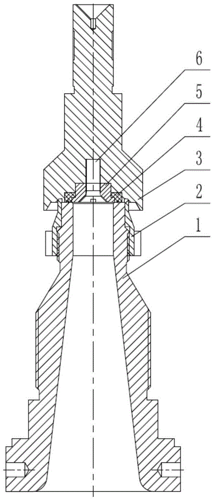
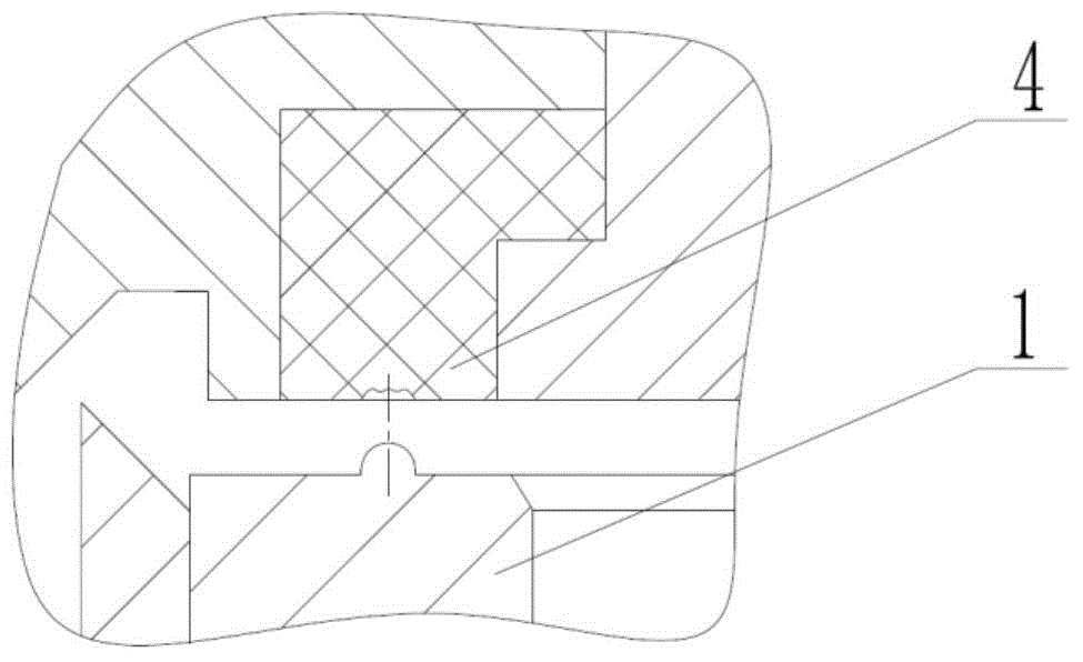
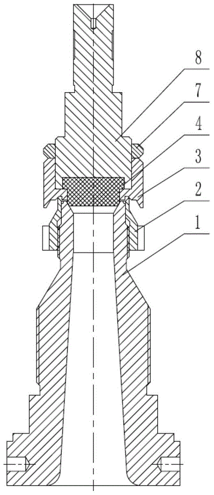
[0019] Such as image 3 As shown in the present invention, a tapered surface soft sealing structure for safety valves, which includes a boss-shaped valve seat 1, the top of the valve seat 1 is embedded in the bottom of the groove-shaped recoil disc 3, through the lower adjustment ring 2 Connect the top of the valve seat 1 to the bottom of the recoil disc 3 with threads. The gap between the recoil disk 3 and the lower adjustment ring 2 can be changed by adjusting the lower adjustment ring 2 , and a pressure accumulator structure is formed between the lower adjustment ring 2 , the recoil disk 3 and the sealing block 4 .

[0020] The groove of recoil disk 3 is plugged into "T" shape sealing block 4, and the lower end of this "T" shape sealing block 4 stretches into the t...


PUM


Abstract

The invention provides a conical surface soft sealing structure for a safety valve. The conical surface soft sealing structure comprises a boss-shaped valve seat. The top end of the valve seat is embedded into the bottom of a groove-shaped recoil disc. The top end of the valve seat is connected with the bottom of the recoil disc through a lower adjusting ring in a threaded mode. A groove in the recoil disc is filled with a T-shaped sealing block. The lower end of the T-shaped sealing block stretches into the top end of the valve seat. A guide rod is arranged above the recoil disc. The guide rod is connected into the recoil disc in a threaded mode. The guide rod and the recoil disc are fixed to prevent loosening through a locking nut. The guide rod presses the sealing block embedded in the recoil disc. Meanwhile, the recoil disc has the function of a pressing block. The sealing block, the recoil disc, the guide rod and the locking nut form an integrally-moving assembly. A conical surface sealing mode is adopted for the sealing face where the valve seat makes contact with the sealing block. By means of the conical surface soft sealing structure for the safety valve, it is guaranteed that the valve is opened precisely, sealed reliably, discharged stably and capable of returning back to the valve seat at the right moment at the normal temperature ranging from -46 DEG C to 200 DEG C and at the low temperature ranging from -46 DEG C to -200 DEG C.

Description

technical field [0001] The invention relates to a safety valve, in particular to a soft sealing structure of a conical surface for a spring direct load type safety valve, which can be applied to normal temperature working conditions (-46°C to 200°C) and low temperature working conditions (-46°C to - 200°C). Background technique [0002] The safety valve is an automatic valve that uses the force of the medium itself to discharge a certain quality of fluid without any external force to prevent the pressure from exceeding the rated safety value. When the pressure returns to normal, the valve closes again and prevents the medium from continuing to flow out. Cryogenic safety valves are widely used in air separation, LNG, LPG, polysilicon and other industries, and are an important product branch in the field of safety valves, with broad market demand. In related chemical fields, especially cryogenic equipment and oxygen medium equipment in the field of air separation, due to ver...

Claims


Application Information

Patent Timeline
IPC IPC(8): F16K1/36F16K1/46F16K1/32F16K17/20
CPCF16K1/32F16K1/36F16K1/46F16K17/20
Inventor 赵益春翟启超刘殿坤马静段淼淼李确高杨
Owner BEIJING AEROSPACE PETROCHEM TECH & EQUIP ENG CORP LTD
Why Eureka
Try Eureka