Electric-pneumatic integrated hose connector

A connector, integrated technology, applied in the direction of hose connection device, connection, connection component installation, etc., can solve the problems of increasing labor intensity of workers, affecting the safety of train operation, easy to be stolen, etc., to reduce labor intensity of workers, improve The effect of continuous hanging efficiency and good anti-theft performance

Active Publication Date: 2015-03-25
CRRC YANGTZE CO LTD
View PDF6 Cites 1 Cited by
  • Summary
  • Abstract
  • Description
  • Claims
  • Application Information

AI Technical Summary

Problems solved by technology

Compared with the traditional air brake device, this not only increases the labor intensity of workers, but also increases the train connection time, which affects the efficiency of train transportation, and the workshop connection cables are exposed outside the end of the vehicle, which is easy to be stolen, thus affecting the train. safe operation
In addition, since the hose connectors and workshop connection cables are arranged at the end of the vehicle, they are prone to collisions and accidents during the operation of the vehicle, which brings great inconvenience to the design of loading and operation and maintenance.
[0005] How the workshop connection device of the ECP brake system can realize the connection between vehicles without changing the traditional operating habits of the vehicle connection personnel, without increasing the labor intensity of the workers and the train connection time, and has good anti-theft performance has always been a technology in the art. The problem that personnel are trying to overcome is also the bottleneck that restricts the application of ECP braking technology on railway wagons in my country

Method used


Image

  • Electric-pneumatic integrated hose connector
  • Electric-pneumatic integrated hose connector
  • Electric-pneumatic integrated hose connector

Examples


Embodiment Construction

[0025] The present invention will be further described in detail below in conjunction with the accompanying drawings and specific embodiments.

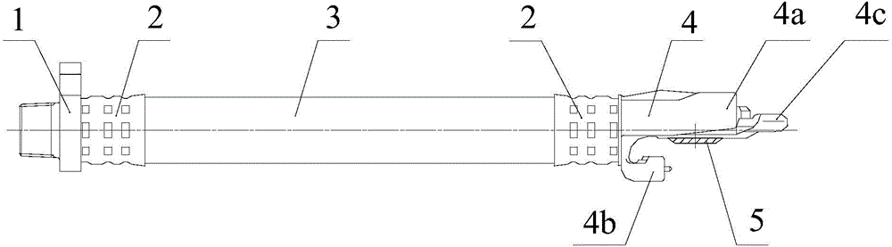
[0026] like figure 1 The shown electric-pneumatic integrated hose connector includes a rubber hose 3 , a hollow threaded joint 1 , a hollow connector body 4 and a double-strand cable 7 arranged in the rubber hose 3 . One end of the soft rubber tube 3 is connected to the hollow threaded joint 1 and tightened with a ferrule 2. The other end of the rubber hose 3 is connected to the hollow connector body 4 and tightened with a ferrule 2. and the hollow connector body 4 communicate with each other to form the passage of the air passage. In addition, a hollow hose gasket 5 is placed in the center hole 4.1 of the hollow connector body 4 to realize the sealing of the air passage. The hollow hose gasket 5 is also connected with the hollow hose gasket 5. The connector body 4 communicates.

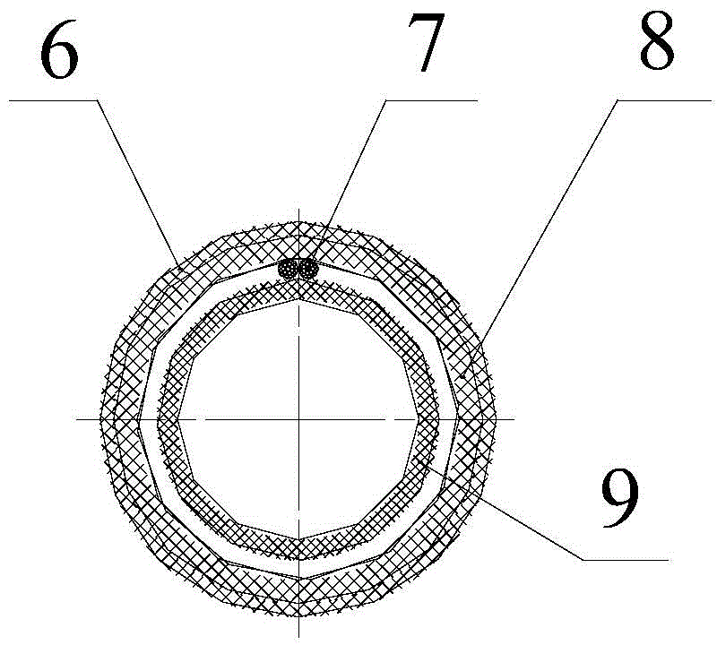
[0027] like figure 2 As shown, the rubber hose 3 o...


PUM


Abstract

The invention discloses an electric-pneumatic integrated hose connector which comprises a rubber hose, a hollow threaded joint connected to one end of the rubber hose and a hollow connector body connected to the other end of the rubber hose, wherein the rubber hose, the hollow threaded joint and the hollow connector body are communicated with one another to form an access of a wind path; a twin-cord cable wound in a spiral manner is arranged in the rubber hose, the end heads at the two ends of the twin-cord cable extend out of the rubber hose to realize communication between a circuit and the wind path simultaneously. The twin-cord cable is arranged inside electric-pneumatic integrated hose connector, wound in the spiral manner and not exposed, so that the twin-cord cable not only can be adaptive to hose bending, but also can guarantee good burglar resistance, and is safe and reliable. Besides, when the electric-pneumatic integrated hose connector is arranged, a first socket can peripherally rotate in an insulated hemispherical sleeve to meet the needs that the first socket is forced to rotate by a plug when the hollow connector rotates and is engaged, and therefore, the mounting is convenient, the train coupling efficiency can be improved, and the labor intensity of the workers can be relieved.

Description

technical field [0001] The invention relates to the technical field of railway freight car braking, in particular to an electric-pneumatic integrated hose connector used for the air circuit and circuit of the braking system between railway freight cars. Background technique [0002] Domestic freight cars have always used air waves to transmit braking signals. There is only one air path running through the entire train. The connection between vehicles uses traditional air hose connectors to connect this air path. When connecting the hose connectors, pull The moving hose drives the connector bodies on the hose connector to rotate and mesh with each other, and is limited by the upper and lower stoppers of the connector body. Because the air wave transmits the braking signal at a slow speed, the braking and release of the vehicles in the train are not synchronized. [0003] With the needs of the rapid development of the national economy, the axle load and speed of railway freig...

Claims


Application Information

Patent Timeline
Patent Type & Authority Applications(China)
IPC IPC(8): F16L33/01H01R31/06H01R13/73
CPCF16L33/01H01R13/745H01R31/06
Inventor 涂智文刘凤伟王宝磊姜瑞金王高睢维伏铁军
Owner CRRC YANGTZE CO LTD
Why Eureka
Try Eureka