Dynamic sealing structure of material tester resistant to high-low temperature high-pressure hydrogen gas environment

A dynamic sealing structure, high-pressure hydrogen technology, applied in the direction of analysis materials, measuring devices, instruments, etc., can solve the problems of reducing the reliability of dynamic sealing, dynamic sealing difficulties, leakage, etc., to improve reliability and service life, and avoid dynamic sealing piece of effect

Inactive Publication Date: 2015-03-25
ZHEJIANG UNIV
View PDF6 Cites 4 Cited by
  • Summary
  • Abstract
  • Description
  • Claims
  • Application Information

AI Technical Summary

Problems solved by technology

However, the development of this type of equipment faces a common problem, that is, the leakage protection of high-pressure hydrogen in the environmental chamber must adopt an effective dynamic sealing structure
With the expansion of the test temperature range, the influence of temperature on the dynamic sealing material increases the difficulty of dynamic sealing.
Low temperature will increase the friction coefficient of the sealing material and accelerate the wear of the dynamic seal, resulting in leakage, while high temperature will easily cause the deterioration of the sealing material and seriously reduce the reliability of the dynamic seal
[0004] At present, there is no sealing material that can withstand both low temperature and high temperature and has good resistance to hydrogen embrittlement.
However, there is no effective solution to the high-low temperature dynamic sealing problem of the high-pressure hydrogen environment material testing machine, which seriously restricts the widening of the material testing machine's temperature range.

Method used


Image

  • Dynamic sealing structure of material tester resistant to high-low temperature high-pressure hydrogen gas environment
  • Dynamic sealing structure of material tester resistant to high-low temperature high-pressure hydrogen gas environment

Examples


Embodiment Construction

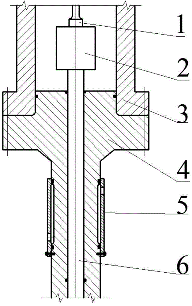
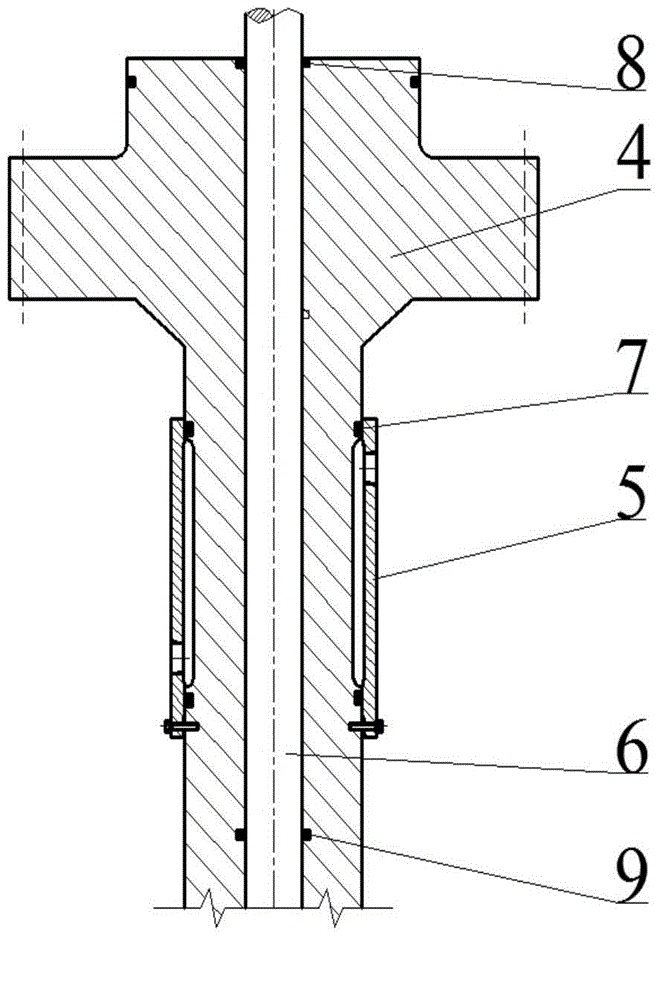
[0017] The dynamic sealing structure of the high-low temperature, high-pressure hydrogen environment-resistant material testing machine in this embodiment includes an environmental box body 3, an environmental box sealing seat 4 and a loading rod 6, and the upper surface of the environmental box sealing seat 4 has a boss structure. The boss structure cooperates with the shape of the opening end of the environmental box 3 to realize the sealing of the environmental box 3 .

[0018] The bottom of the environmental box seal seat 4 has a tubular part extending downwards, and the inside has a through hole through which the loading rod 6 extends into the inside of the environmental box 3; the loading rod 6 and the A guide ring 8 and a dynamic seal 9 are respectively arranged on the gap cylindrical surface of the environmental box seal seat 4; the use of the guide ring 8 and the dynamic seal 9 makes the loading rod 6 not in direct contact with the environmental box seal seat 4; the gu...


PUM


Abstract

The invention relates to the material mechanical performance test equipment and aims to provide a dynamic sealing structure of a material tester resistant to a high-low temperature high-pressure hydrogen gas environment. The dynamic sealing structure comprises an environment box, wherein a tubular part downwards extending is arranged on the bottom of the environment box, and a penetrating through hole is formed inside the tubular part; a guide ring and a dynamic sealing part are respectively arranged on a loading end at the two ends of the through hole and a clearance cylindrical surface of an environment box sealing base, so that the loading rod does not directly contact with the environment box sealing base; a temperature control jacket is arranged at the outer side of the tubular part between the guide ring and the dynamic sealing part in an annular manner. The dynamic sealing structure can be used for controlling the temperature on a dynamic sealing part, avoiding the influences of the test gas temperature in the environment box on the sealing part, preventing abrasion due to direct contact with metal between the loading rod and the environment box sealing base, improving the sealing reliability and prolonging the service life, avoiding frequently replacing the sealing part, and realizing the dynamic sealing of the high pressure hydrogen gas environment material tester without being limited by the gas test temperature of the environment box.

Description

technical field [0001] The invention belongs to the field of development of material mechanical performance testing equipment, and in particular relates to a material test motorized sealing structure resistant to high, low temperature, and high pressure hydrogen environments. Background technique [0002] Hydrogen energy has the advantages of high conversion efficiency, clean combustion products and diversified uses, and is an important secondary energy source in the new century. Realizing the industrialization of hydrogen energy utilization requires the use of a large number of high-pressure equipment. They work in a high-pressure hydrogen environment for a long time, and may cause material failure due to hydrogen embrittlement, resulting in catastrophic consequences. However, the temperature is not always kept at room temperature during the working process, and the change of temperature will cause a large change in the hydrogen embrittlement susceptibility of the material,...

Claims


Application Information

Patent Timeline
Patent Type & Authority Applications(China)
IPC IPC(8): G01N3/02
Inventor 顾超华赵永志周池楼张鑫郑津洋孙国有
Owner ZHEJIANG UNIV
Why Eureka
Try Eureka