

IC card service life testing method and device
A technology of life test and card reader, which is applied in the field of mechatronics, can solve the problem that the clamping position is not easy to fit the card reader, and achieve the effects of easier plugging and unplugging, saving human resources and convenient operation
- Summary
- Abstract
- Description
- Claims
- Application Information
AI Technical Summary
Problems solved by technology
Method used
Image

Examples
Embodiment Construction
[0034] In order to provide an implementation plan for automatically sucking and clamping the IC card and accurately fixing the position of the IC card, the embodiment of the present invention provides a method and device for testing the service life of the IC card. The preferred embodiment of the present invention will be described below in conjunction with the accompanying drawings .
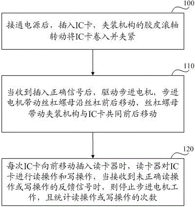
[0035] refer to figure 1 As shown, a kind of IC card service life testing method that the embodiment of the present invention provides, this method comprises the steps:
[0036] Step 100: After turning on the power, insert the IC card, and the rubber roller of the clamping mechanism rotates to draw in and clamp the IC card.
[0037] Specifically, the IC card service life testing device includes a shell, and the position corresponding to the IC card involved in the shell is provided with a card insertion guide groove from the outside, so that the IC card can be inserted into the correct positio...
PUM
 Abstract
Description
Claims
Application Information