A Flow Compensation Method for Magnetic Resonance Imaging System

A technology of nuclear magnetic resonance imaging and compensation method, which is applied to the measurement of magnetic variables, measurement devices, instruments, etc., can solve the problems of reduced echo signal amplitude, serious image pulsation artifacts, and image quality degradation, and achieves a reduced artifact reduction. Effect

Active Publication Date: 2018-02-09
BEIJING WANDONG MEDICAL TECH CO LTD
View PDF9 Cites 0 Cited by
  • Summary
  • Abstract
  • Description
  • Claims
  • Application Information

AI Technical Summary

Problems solved by technology

In the conventional MRI sequence, by controlling the radio frequency pulse and the gradient amplitude and timing imaging of the three encoding directions of Gx, Gy, and Gz, for static tissues, the cumulative phase of the gradients in the three directions after echo acquisition is zero, but the flow The liquid (blood, breathing, heartbeat, gastrointestinal peristalsis and other physiological movements) has a certain flow velocity, which will cause the phase accumulation of the spin magnetization vector in the gradient direction, which will cause the amplitude of the echo signal to decrease, and the image pulsation artifacts Severe shadowing, degraded image quality

Method used


Image

  • A Flow Compensation Method for Magnetic Resonance Imaging System
  • A Flow Compensation Method for Magnetic Resonance Imaging System
  • A Flow Compensation Method for Magnetic Resonance Imaging System

Examples


Embodiment

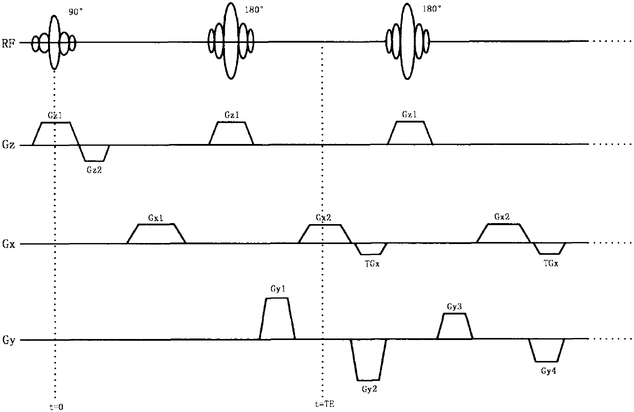
[0034] Taking the flow compensation in the frequency encoding direction as an example, the compensation in the layer selection direction and the phase encoding direction are the same:

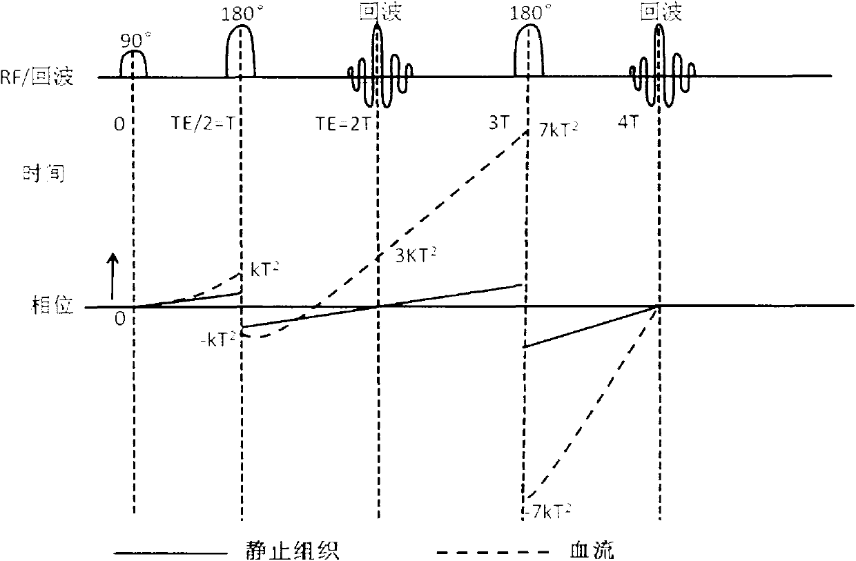
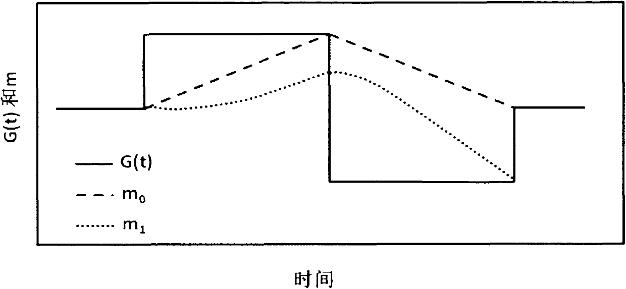
[0035] (1) figure 1 is the conventional FSE imaging sequence diagram, figure 2 is the accumulated phase of stationary tissue and flowing fluid during FSE multi-echo acquisition, image 3 , Figure 4 Zeroing compensation gradient design for zero-order and first-order gradient moments, respectively.

[0036] (2) Set the initial parameters, the gradient strength G is 20mT / m, the plateau period of the compensated gradient pulse is 200μs, the gradient rise and fall length is 1ms, the data sampling time is 20μs, the number of sampling points is 256, and the dead time of the receiver is 870μs.

[0037] (3) Figure 5 For the flow compensation sequence used in the present invention, the sequence is at figure 1 On the basis of conventional FSE, three gradients G are applied between the 90° RF pulse...


PUM


Abstract

The invention discloses a flow compensation method for a magnetic resonance imaging system, which is characterized in that it comprises the following steps: (1) between the 90° radio frequency pulse and the 180° radio frequency pulse sequence of a fast spin echo (FSE) sequence, In the direction of frequency encoding, gradient combined pulses satisfying flow compensation are applied. (2) Before the 180° radio frequency pulse, the dispersal gradient is applied before the signal acquisition gradient, and the compensation gradient is applied after the acquisition gradient. At this time, the signal acquisition gradient, the dispersal gradient, and the compensation gradient together constitute the first-order velocity compensation gradient. (3) Set the phase encoding gradient amplitude to zero, set the sequence timing, adjust the gradient amplitude, and make the amplitude of each echo signal peak on the echo chain reach the maximum value, and complete the sequence debugging. (4) Output the sequence to the spectrometer to realize flow compensation. The flow compensation provided by the present invention can significantly suppress flow artifacts and image blur caused by cerebrospinal fluid and spinal cord flow, thereby reducing image artifacts caused by physiological movements such as blood flow or periodic motion.

Description

technical field [0001] The invention belongs to the technical field of magnetic resonance imaging, in particular to a flow compensation method for a nuclear magnetic resonance imaging system. Background technique [0002] Magnetic resonance imaging (MRI) has become a very important imaging method in medical diagnosis. Conventional magnetic resonance imaging sequence, by controlling the radio frequency pulse and the gradient amplitude and timing imaging of the three encoding directions of Gx, Gy, and Gz, for static tissues, the cumulative phase of the gradients in the three directions after echo acquisition is zero, but the flow The liquid (blood, breathing, heartbeat, gastrointestinal peristalsis and other physiological movements) has a certain flow velocity, which will cause the phase accumulation of the spin magnetization vector in the gradient direction, which will cause the echo signal amplitude to decrease, and the image pulsation artifacts shadowing is severe and imag...

Claims


Application Information

Patent Timeline
Patent Type & Authority Patents(China)
IPC IPC(8): G01R33/563
Inventor 王为民谷长春庞佩佩
Owner BEIJING WANDONG MEDICAL TECH CO LTD
Why Eureka
Try Eureka