A frame structure for liquid crystal display
A liquid crystal display and frame technology, which is applied in nonlinear optics, instruments, optics, etc., can solve the problems that the liquid crystal panel cannot be tightly fixed, the frame cannot be found, and electronic products cannot be designed without a frame, so as to achieve a wide display screen and improved Aesthetics, the effect of increasing practicality
- Summary
- Abstract
- Description
- Claims
- Application Information
AI Technical Summary
Problems solved by technology
Method used
Image

Examples
Embodiment 1
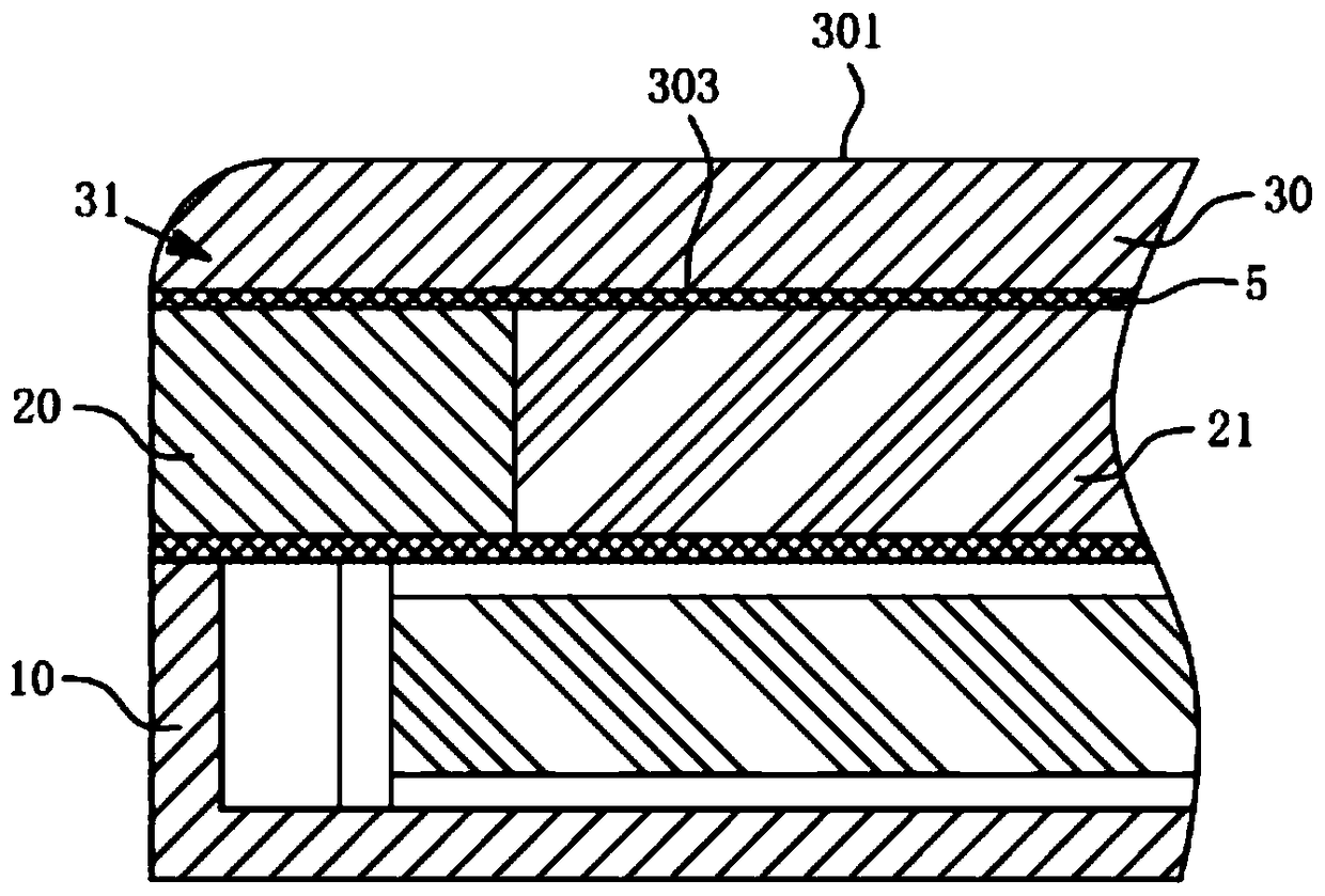
[0024] like figure 1 As shown, in this embodiment, the light-transmitting structure 31 and the cover plate 30 are integrated structures, the panel frame 20 is used to support the light-transmitting structure 31 and the cover plate 30 , and the light-transmitting structure 31 is overlapped on the panel frame 20 . Wherein, the cover plate 30 is provided with a first light-emitting surface 301 and a bottom surface 303, and the light-transmitting structure 31 is an arc surface connecting the first light-emitting surface 301 and the bottom surface 303, and the section of the arc surface is fan-shaped. Specifically, the arc-shaped surface of the light-transmitting structure 31 can refract the display light of the liquid crystal panel 21. Compared with the traditional cover plate 30 that displays the light range of the liquid crystal panel 21, the integrated structure of the light-transmitting structure 31 and the cover plate 30 displays a range of It is wider, and in the power-on di...
Embodiment 2
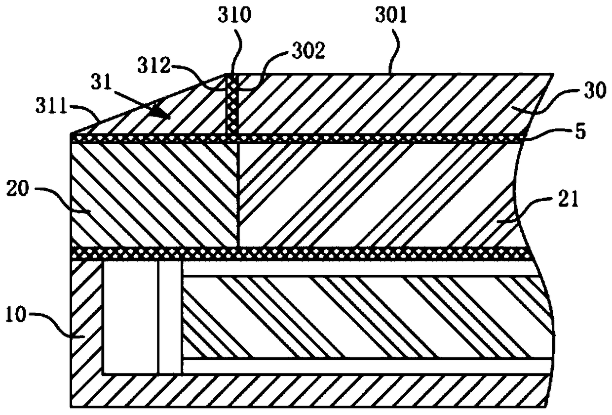
[0026] like figure 2 As shown, in this embodiment, the light-transmitting structure 31 and the cover plate 30 are detachable structures, the light-transmitting structure 31 is provided with a second light-emitting surface 311 and an inner wall surface 312, and the cover plate 30 is provided with at least a first light-emitting surface 301 and an outer wall surface. wall 302 . Wherein, the first light-emitting surface 301 is connected with the second light-emitting surface 311 to form a display screen of an electronic device, and the second light-emitting surface 311 is a slope, so that the cross section of the light-transmitting structure 31 is triangular, and the light-transmitting structure 31 is a prism. A transparent glue 310 is provided between the inner wall surface 312 and the outer wall surface 302 to make the light-transmitting structure 31 and the cover plate 30 closely adhere to form a detachable structure without affecting the emission of display light by the liqu...
Embodiment 3
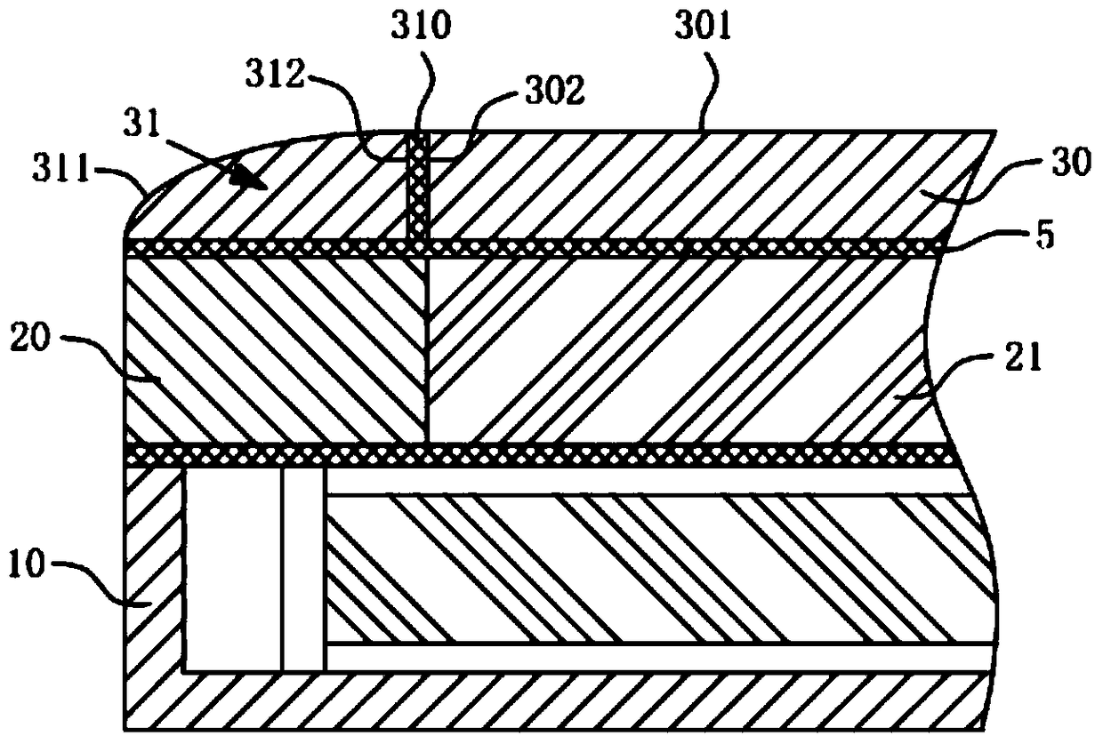
[0029] like image 3 As shown, in this embodiment, the light-transmitting structure 31 and the cover plate 30 are detachable structures, the light-transmitting structure 31 is provided with a second light-emitting surface 311 and an inner wall surface 312, and the cover plate 30 is provided with at least a first light-emitting surface 301 and an outer wall surface. wall 302 . Wherein, the first light-emitting surface 301 is connected with the second light-emitting surface 311 to form a display screen of an electronic device, and the second light-emitting surface 311 is a curved surface, so that the cross section of the light-transmitting structure 31 is fan-shaped, and the light-transmitting structure 31 is a prism. A transparent glue 310 is provided between the inner wall surface 312 and the outer wall surface 302 to make the light-transmitting structure 31 and the cover plate 30 closely adhere to form a detachable structure without affecting the emission of display light by ...
PUM
 Abstract
Description
Claims
Application Information
 - R&D
- Intellectual Property
- Life Sciences
- Materials
- Tech Scout
- Unparalleled Data Quality
- Higher Quality Content
- 60% Fewer Hallucinations
Browse by: Latest US Patents, China's latest patents, Technical Efficacy Thesaurus, Application Domain, Technology Topic, Popular Technical Reports.
© 2025 PatSnap. All rights reserved.Legal|Privacy policy|Modern Slavery Act Transparency Statement|Sitemap|About US| Contact US: help@patsnap.com