Personal 3D and 2d viewing device

a viewing device and 3d technology, applied in the field of personal 3d and 2d (2 dimensional) viewing devices, can solve the problems of image resolution, size limitation of useable screens, side methods that are flawed, etc., and achieve the effect of improving digital content viewing and facilitating physical separation of two display screens

Inactive Publication Date: 2019-10-31
RICHARDSON STUART BROOKE
View PDF3 Cites 5 Cited by
  • Summary
  • Abstract
  • Description
  • Claims
  • Application Information

AI Technical Summary

Benefits of technology

[0012]The three disclosed problems associated with the side-by-side methodology are here solved by placing an optical system in front of each eye, which allows the display screens to be physically displaced, hence spatially separated, thereby bypassing the problem of the limited spacing between the user's two eyes.
[0013]This new spatial separation technique allows larger display screen sizes to be used, and also wider display screens—i.e. display screens that are widescreen formatted. The use of larger display screens puts to an immediate end the aforementioned problem of resolution, since 5.5-inch diagonally measured display screens are now being manufactured in the industry with UHD resolution. The new spatial separation technique of the current invention also puts an end to the aforementioned widescreen limitations of the side-by-side paradigm, allowing for the first time true native widescreen viewing in a head-worn 3D / 2D device. It is this combination of high resolution and native widescreen, via this optical separation technique, which makes the detailed invention so innovative and unprecedented.
[0014]The two optical systems within the described apparatus are bisymmetrically arranged, as front-surface mirror-opposites of each other. Each optical system is composed of a converging lens and a front-surface mirror. It is the front surface mirrors in the device which allow the flexible placement of the display screens within the apparatus, and in this case the front-surface mirrors deflect the user's gaze both upward and outward, thus allowing the display screens to be placed well apart from one another. This wide spacing is what allows the display screens to be much larger than those used in the side-by-side methodology. Thus the first problem of the side-by-side method is solved here—that of the allowance of larger display screen sizes.
[0019]It is this very special combination of elements—the front-surface mirrors which facilitate the physical separation of the two display screens, the odd shape and extreme compound angle of those front-surface mirrors which creates an intended optical illusion, the rotational displacement that their extreme angles create, the rotational compensation realized in the final placement of the display screens, and the widescreen ‘shaping’ of all optical elements—converging lenses and front-surface mirrors, as well as the display screens—which together allow such a vast improvement in digital content viewing for a head-mounted device.

Problems solved by technology

The side-by-side method is a flawed paradigm as it imposes three severe limitations; the first being image resolution due to the ‘pixel density’ problem; the second being the size limitation of useable screens owing to the fact that the distance between the eyes of humans is small; and the third being widescreen viewing, which is directly related to the previous two problems.
Devices using the side-by-side method do not offer native widescreen viewing because doing so would severely limit the total size of their display screens, since it is the width of side-by-side screens that is the limitation, and since those manufacturers who produce such devices want to take advantage of the fact that screen height is not limited within that paradigm.
Because of these stated problems, devices based on the side-by-side method are very poor choices for the viewing of modern TV shows, cinematic movies, high-end video games, high-resolution computer desktops, eSports streams, or any digital content that requires a combination of high resolution and native widescreen formatting.

Method used


Image

  • Personal 3D and 2d viewing device
  • Personal 3D and 2d viewing device
  • Personal 3D and 2d viewing device

Examples


Embodiment Construction

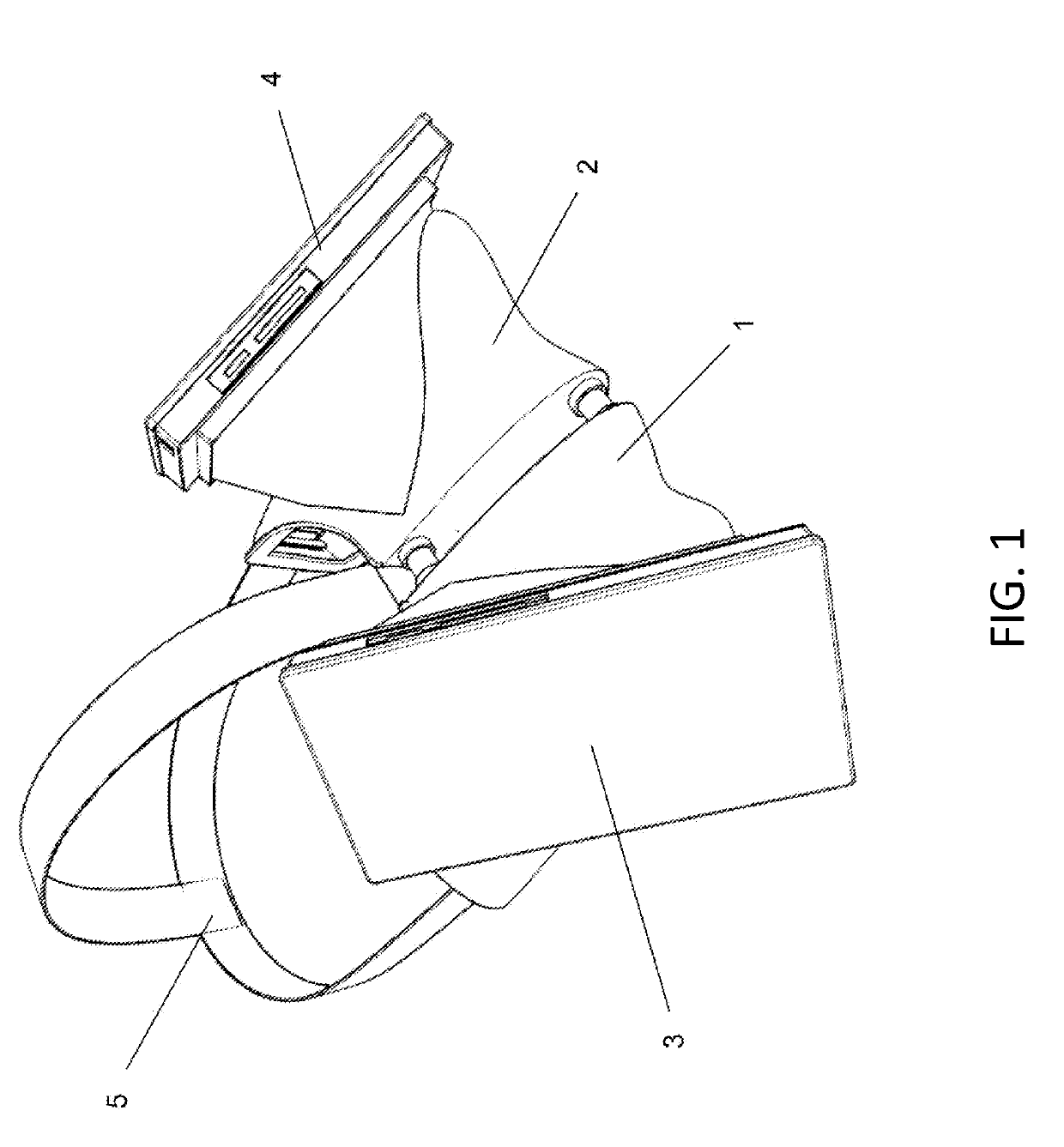
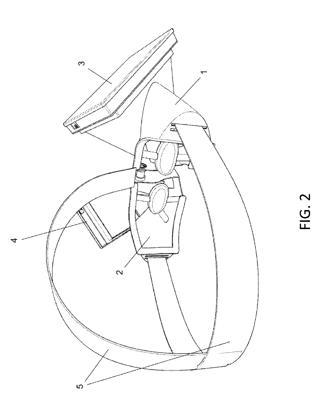
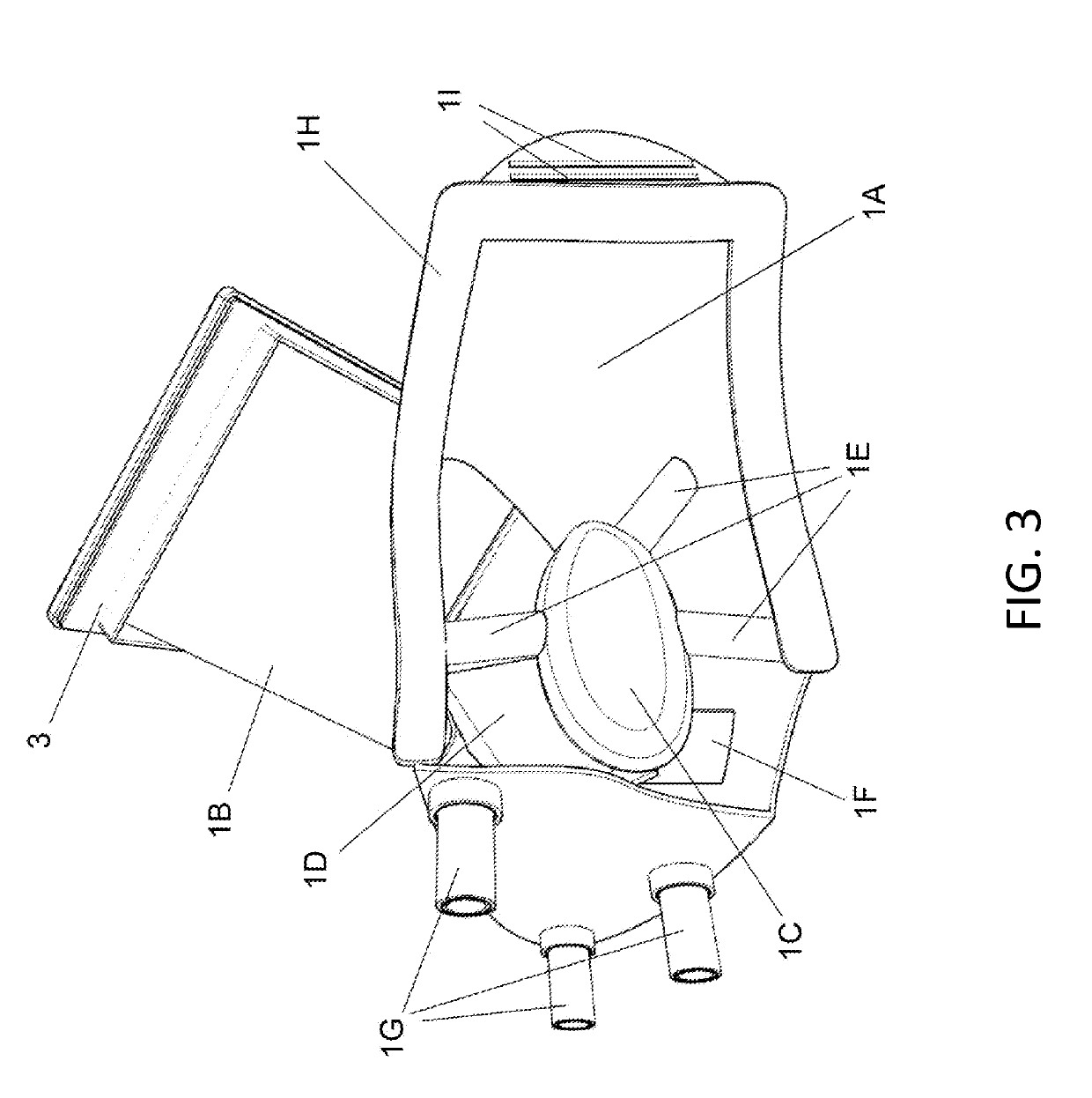
[0041]The following text describes in detail the functionality of the invention, along with descriptions of the various assemblies and parts, with reference to the associated drawings which are included for clarification of said text.

[0042]This text assumes an XYZ Cartesian coordinate system based in the normal three dimensions of space, within which the Y axis is along the forward line of sight of the user who is wearing the apparatus in question, in other words front and back of the user; the X axis runs left and right of the user; and the Z axis runs up and down from the user's perspective.

[0043]This invention is a VR (Virtual Reality) system which features a head-mounted apparatus that the user dons on his / her face using the included strap-based system, so that the user's eyes are optically interfaced with the apparatus. The strap-based system is user-adjustable, to accommodate different head sizes, and made of flexible material to provide constant tension for the sake of keepin...


PUM


Abstract

A personal, portable Virtual Reality system comprising a headset, i.e., a head-worn device, which itself contains two separate 16:9, landscape-oriented optical systems, one for each of the user's eyes, and two 16:9 display screens, the combination of which creates an optical illusion within the viewing field of the user, which illusion tricks the user's brain into thinking that the user is seeing a singular 16:9, landscape-oriented 3D and / or 2D screen, which singular virtual screen the user perceives as being magnified in size, and extended many feet into the distance, rather than the two separate display screens inside said headset, which are in reality small and at very close range. Said VR system may also comprise a shoulder-array which offloads the weight of the processing and battery hardware from the headset, various means of protecting the user from direct WIFI signals emanating from the apparatus, and various versions of the headset offering different options for fixed and / or one or two user-installed smartphones, which smartphones would be used as the display screen(s) and processing / battery hardware of said system. Said system may also comprise a pair of video cameras, to capture stereo-optic environmental imagery for superimposing onto the existing imagery within the device, and integrated audio headphones.

Description

CROSS REFERENCE TO RELATED APPLICATIONS[0001]This Non-provisional Patent Application includes extended temporal protection under 35 U.S.C. § 119(e) via Provisional Patent Application No. 62 / 489,428, filed in the U.S. on Apr. 24, 2017 by the same sole inventor, Stuart Brooke Richardson.BACKGROUND OF THE INVENTIONField of Invention[0002]This invention relates to the field of personal, head-worn 3D (3 Dimensional) and 2D (2 Dimensional) viewing devices.Related Art[0003]Because the eyes of humans are spread a few inches apart, each eye experiences a unique perspective that is slightly shifted from the other—this is a principal widely known as ‘parallax’. Our brains combine the two 2-dimensional images that our eyes receive into a singular virtual 3D ‘image’—this is how humans perceive depth in the natural world.[0004]Virtual parallax, on the other hand, mimics optical parallax by presenting the user with synthesized image pairs, one image for the right eye and one for the left eye. Such...

Claims


Application Information

Patent Timeline
Patent Type & Authority Applications(United States)
IPC IPC(8): G02B27/01G02B27/02G02B27/22G03B35/18
CPCG03B35/18G02B27/2235G02B27/02G02B27/0172G02B2027/0134G06T3/00G02B30/35
Inventor RICHARDSON, STUART BROOKE
Owner RICHARDSON STUART BROOKE
Why Eureka
Try Eureka