Shifting register unit, driving method of shifting register unit, shifting register circuit and display device

A technology of shift register and reset terminal, which is applied in static memory, digital memory information, instruments, etc., can solve the problem of short effective charging time of pixels, achieve the goal of increasing effective charging time of pixels, simplifying circuit structure, and reducing falling edge time Effect

Active Publication Date: 2015-03-25
HEFEI XINSHENG OPTOELECTRONICS TECH CO LTD +1
View PDF6 Cites 24 Cited by
  • Summary
  • Abstract
  • Description
  • Claims
  • Application Information

AI Technical Summary

Problems solved by technology

[0006] The present invention provides a shift register unit and its driving method, a shift register circuit, and a display device, which are used to solve the problems caused by the long falling edge time (Tf) of the gate drive signal in the prior art. The problem of short pixel effective charging time (Teff)

Method used


Image

  • Shifting register unit, driving method of shifting register unit, shifting register circuit and display device
  • Shifting register unit, driving method of shifting register unit, shifting register circuit and display device
  • Shifting register unit, driving method of shifting register unit, shifting register circuit and display device

Examples


Embodiment Construction

[0047] Embodiments of the present invention provide a shift register unit and its driving method, a shift register circuit, and a display device, which realize a shift with short falling edge time output by the shift register unit and long effective charging time of pixels. A bit register unit, a shift register circuit and a display device with simple structure and low power consumption.

[0048] The specific implementation of the present invention will be described in detail below in conjunction with the accompanying drawings and specific embodiments.

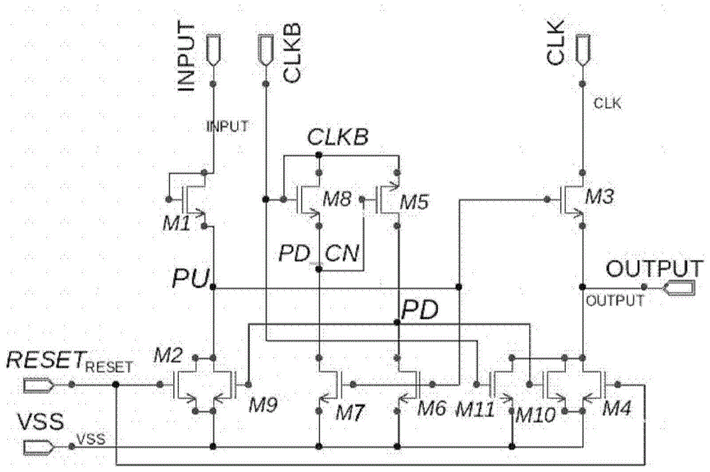
[0049] refer to Figure 5 , Figure 5 is a block diagram showing a shift register unit 500 according to an embodiment of the present invention. The shift register unit 500 includes a charging module 501 , a pull-up module 502 , a first pull-down control module 530 , a second pull-down control module 504 , a first pull-down module 505 , a second pull-down module 506 and a reset module 507 .

[0050] One end of the charging m...


PUM


Abstract

The invention provides a shifting register unit, a driving method of the shifting register unit, a shifting register circuit and a display device. The shifting register unit comprises a charging module, a pull-up module, a first pull-down control module, a second pull-down control module, a first pull-down module, a second pull-down module and a reset module. One end of the charging module is connected with an input end, the other end of the charging module is connected with a pull-up node, and the charging module is used for generating a pull-up signal; one end of the pull-up module is connected with the pull-up node, the other end of the pull-up module is connected with a first clock signal end, and the pull-up module is used for charging an output end; one end of the first pull-down control module is connected with a second clock signal end, the other end of the first pull-down control module is connected with a low-voltage end, and the first pull-down control module is used for generating a pull-down control signal; one end of the second pull-down control module is connected with a pull-down control node, the other end of the second pull-down control module is connected with the pull-up node, and the second pull-down control module is used for generating a pull-down signal; one end of the first pull-down module is connected with a first reset end, the other end of the first pull-down module is connected with the output end, and the first pull-down module is used for discharging the output end; one end of the second pull-down module is connected with a pull-down node, the other end of the second pull-down module is connected with the output end, and the second pull-down module is used for discharging the output end; one end of the reset module is connected with a second reset end, the other end of the reset module is connected with the pull-up node, and the reset module is used for resetting the pull-up node.

Description

technical field [0001] The present invention relates to the field of display technology, and more specifically, to a shift register unit and a driving method thereof, a shift register circuit and a display device. Background technique [0002] Flat-panel displays are widely used because of their ultra-thin and energy-saving features. Shift registers are used in most flat-panel displays. The shift register implemented by the GOA (Gate Drive on Array) method can save the gate drive IC and reduce a manufacturing process, so it not only reduces the manufacturing cost of the flat-panel display. The cost also shortens the manufacturing cycle to a certain extent. [0003] Therefore, GOA technology has been widely used in the manufacture of flat panel displays in recent years. The power consumption of GOA itself is larger than that of ordinary gate drive ICs. In order to reduce the power consumption of the GOA unit itself, 4 or more clock (CLK) signals are often used (the number o...

Claims


Application Information

Patent Timeline
Patent Type & Authority Applications(China)
IPC IPC(8): G09G3/20G11C19/28
CPCG09G3/20G09G2310/0267G09G2320/0223G09G2320/0252G09G2310/0286G11C19/28G09G3/3677G09G5/003G09G2300/0426G09G2310/0251G09G2310/08G09G2330/021
Inventor 杨通马睿王国磊
Owner HEFEI XINSHENG OPTOELECTRONICS TECH CO LTD
Why Eureka
Try Eureka