Display panel and display device

A display panel and display area technology, applied to static indicators, instruments, etc., to achieve the effects of prolonging the effective charging time, reducing load differences, and reducing distances

Active Publication Date: 2019-09-17
BOE TECH GRP CO LTD
View PDF8 Cites 0 Cited by
  • Summary
  • Abstract
  • Description
  • Claims
  • Application Information

AI Technical Summary

Problems solved by technology

[0005] In view of this, an embodiment of the present invention provides a display panel and a display device to solve the problem in the prior art of how to reduce the load difference of each pixel unit in a row of pixel units connected to the shift register unit, and extend each The problem of the effective charging time of the pixel unit

Method used


Image

  • Display panel and display device
  • Display panel and display device
  • Display panel and display device

Examples


Embodiment Construction

[0032] The specific implementation manners of the display panel and the display device provided by the embodiments of the present invention will be described in detail below with reference to the accompanying drawings.

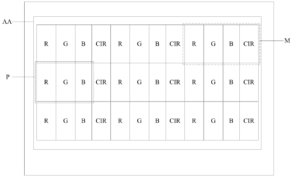
[0033] A display panel provided by an embodiment of the present invention, such as Figure 3a and Figure 3b As shown, it includes: a plurality of pixel units P arranged in an array generally including red sub-pixels R, green sub-pixels G and blue sub-pixels B arranged in the display area AA, and at least the gates arranged in the display area AA drive circuit; where,

[0034] The gate drive circuit includes a plurality of cascaded shift register units, each stage of shift register units is respectively connected to a row of pixel units, and each stage of shift register units includes at least three shift register units in the display area AA Subcircuit CIR.

[0035] In the above-mentioned display panel provided by the embodiment of the present invention, s...


PUM


Abstract

A display panel and a display device are disclosed, the display panel includes: a plurality of pixel units arranged in an array in a display area, and a gate drive circuit arranged at least in the display area, where the gate drive circuit includes a plurality of shift register elements connected in cascade, each level of the plurality of shift register elements is connected respectively with a row of the plurality of pixel units, and each level of the plurality of shift register elements includes at least three shift register sub-circuits in the display area.

Description

technical field [0001] The present invention relates to the field of display technology, in particular to a display panel and a display device. Background technique [0002] In the prior art, a display device generally includes a plurality of pixel units located in a display area, and a gate driver circuit and a source driver located in a frame area in a horizontal direction and a vertical direction. Wherein, the source driver is used to provide data signals to a plurality of pixel units. The gate drive circuit includes multiple cascaded shift register units, each shift register unit corresponds to a row of pixel units, and the multiple shift register units realize the progressive scanning drive of multiple pixel units to control the writing of data signals Into the pixel unit, and then realize the image display. [0003] In the prior art, the shift register unit is generally arranged in the frame area on one side of a row of pixel units, that is, the single-side gate driv...

Claims


Application Information

Patent Timeline
Patent Type & Authority Patents(China)
IPC IPC(8): G09G3/36G09G3/3266
CPCG09G3/3266G09G3/3674G09G2310/0286G09G3/3677G09G2300/0413G09G2300/0804G09G2310/0289G09G2320/0223
Inventor 李全虎
Owner BOE TECH GRP CO LTD
Why Eureka
Try Eureka