Relay control circuit

A relay control and circuit technology, applied in the direction of relays, circuits, electrical components, etc., can solve problems such as jitter, reduce jitter, and ensure effective suction

Active Publication Date: 2016-08-24
EMERSON NETWORK POWER CO LTD
View PDF4 Cites 0 Cited by
  • Summary
  • Abstract
  • Description
  • Claims
  • Application Information

AI Technical Summary

Problems solved by technology

[0003] The technical problem to be solved by the present invention is to provide a relay control circuit for the defects of the relay control circuit in the prior art that the main contacts of the relay vibrate and / or stick due to insufficient voltage and / or large current passing through the relay coil , which makes the output voltage of the AC / DC rectifier module reach the set value to drive the relay to pull in, thereby reducing the jitter of the main contact of the relay and ensuring the effective pull-in of the main contact of the relay

Method used


Image

  • Relay control circuit
  • Relay control circuit
  • Relay control circuit

Examples


Embodiment Construction

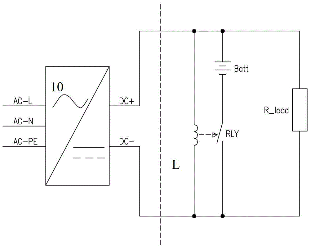
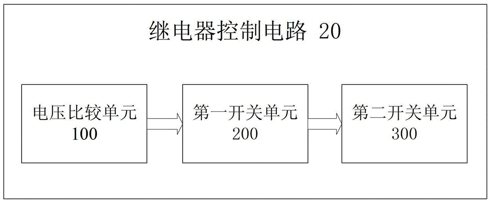
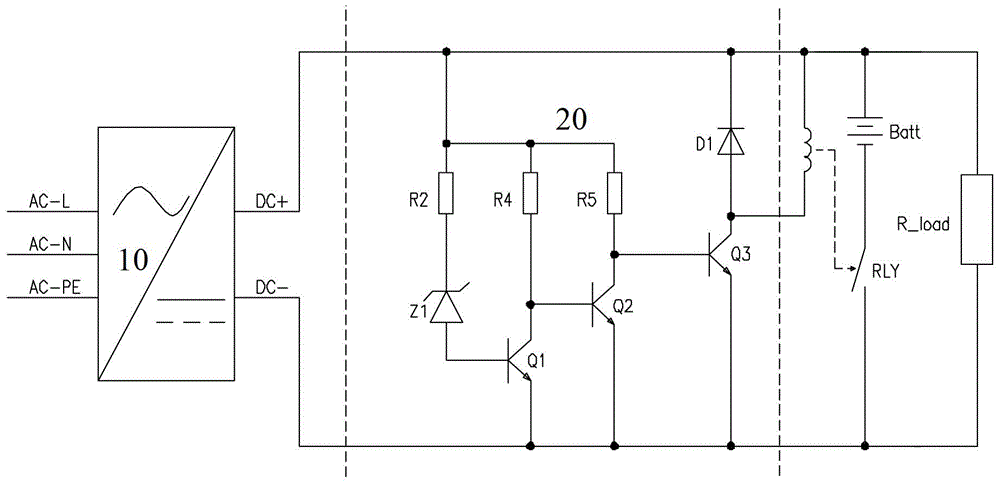
[0025] figure 2 is a functional block diagram of the relay control circuit according to the first embodiment of the present invention. Such as figure 2 As shown, the relay control circuit 20 of the present invention includes a voltage comparison unit 100 , a first switch unit 200 and a second switch unit 300 . The voltage comparison unit 100 can be combined with an AC / DC rectification module (see figure 1 ) connection to receive the rectified output voltage from the AC / DC rectification module. Subsequently, the voltage comparison unit 100 compares the rectified output voltage received from the AC / DC rectification module with the set operating voltage to generate a first switch driving signal. The first switch unit 200 receives the first switch driving signal and turns on or off based on the first switch driving signal, so as to generate a second switch driving signal. The second switch unit receives the second switch driving signal, and is turned on or off based on the s...


PUM


Abstract

The invention relates to a relay control circuit which comprises a voltage comparing unit, a first switch unit and a second switch unit. The voltage comparing unit is used for generating a first switch driving signal based on comparing of rectification output voltage and set operation voltage received from an AC / DC rectifier module. The first switch unit generates a second switch driving signal based on connecting or disconnecting of the first switch signal. The second switch unit generates a relay control signal which controls engaging or disengaging of a main contact of a relay based on connecting or disconnecting of the second switch driving signal. According to the relay control circuit, only when the voltage output by the AC / DC rectifier module reaches a set value, the relay can be driven to be subjected to engaging, accordingly, shaking of the main contact of the relay is lowered, and effective engaging of the main contact of the relay is guaranteed.

Description

technical field [0001] The invention relates to the field of relays, in particular to a relay control circuit for controlling the pull-in of a relay. Background technique [0002] Relays are widely used in communication power supplies as power-on and power-off control devices. figure 1 It shows a power supply circuit that adopts relay control to supply power to a battery or a load in the prior art. Such as figure 1 As shown, the mains current is rectified by the AC / DC rectifier module 10 and directly supplied to the coil L of the relay RLY. Due to the existence of the output capacitor of the AC / DC rectifier module 10, the DC output voltage rises slowly due to the charging of the output capacitor when the AC / DC rectifier module 10 is started. When the minimum pull-in voltage of the relay RLY is reached, the relay RLY starts to pull in, but at this time, the relay RLY has a small magnetic force due to the insufficient voltage of the coil L, and the main contacts often vibra...

Claims


Application Information

Patent Timeline
Patent Type & Authority Patents(China)
IPC IPC(8): H01H47/00
CPCH01H47/02
Inventor 陈兴国
Owner EMERSON NETWORK POWER CO LTD
Why Eureka
Try Eureka