Supercharge Your Innovation With Domain-Expert AI Agents!

Installation device, antenna orientation device, directional antenna system and mobile communication system

A technology for installation devices and orientation devices, which is applied in the direction of antenna supports/installation devices, antennas, electrical components, etc., which can solve problems such as errors, lack of installation directions, and inability to perform addition and subtraction calibration, and achieve the effect of improving accuracy

Active Publication Date: 2015-03-25
GCI SCI & TECH
View PDF5 Cites 1 Cited by
  • Summary
  • Abstract
  • Description
  • Claims
  • Application Information

AI Technical Summary

Problems solved by technology

[0003] There are mainly two existing installation schemes. One is to determine the installation direction of the antenna after visually measuring the azimuth with the aid of a compass. The previous installation direction is compared, and the addition and subtraction calibration cannot be performed
The other is to use a compass and a compass for directional installation. By setting the compass on the antenna column, the angle value on the compass can be used to determine the installation direction of the antenna. However, this solution does not take into account the relationship between the compass and the antenna column. Coaxial problems lead to an error between the installation direction of the antenna and the angle value indicated by the compass. In addition, for different specifications of the antenna column, it is necessary to design a compass of the corresponding specification, which is not suitable for use

Method used


Image

  • Installation device, antenna orientation device, directional antenna system and mobile communication system
  • Installation device, antenna orientation device, directional antenna system and mobile communication system
  • Installation device, antenna orientation device, directional antenna system and mobile communication system

Examples


Embodiment Construction

[0021] The following will clearly and completely describe the technical solutions in the embodiments of the present invention with reference to the accompanying drawings in the embodiments of the present invention. Obviously, the described embodiments are only some, not all, embodiments of the present invention. Based on the embodiments of the present invention, all other embodiments obtained by persons of ordinary skill in the art without making creative efforts belong to the protection scope of the present invention.

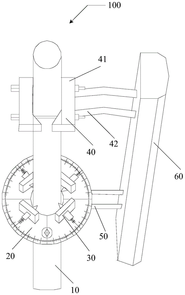
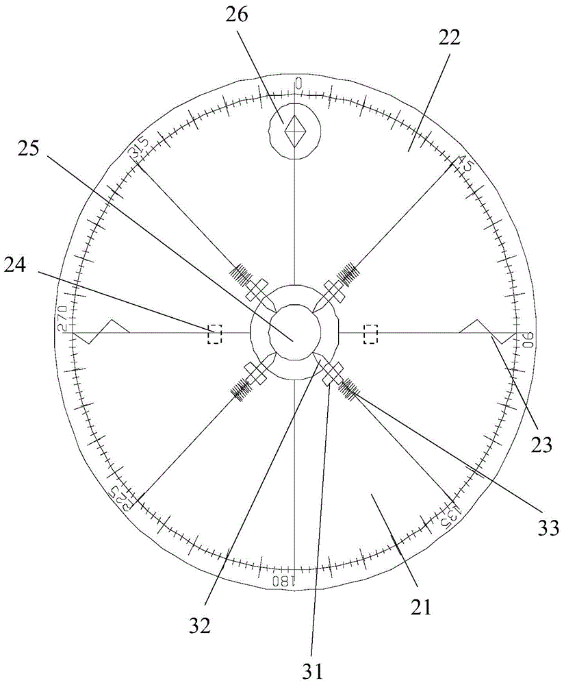
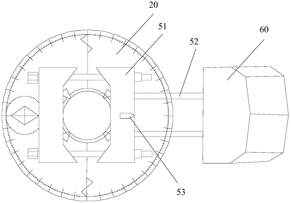
[0022] please participate figure 1 , the embodiment of the present invention provides a directional antenna system 100, the directional antenna system 100 includes an antenna column 10, a dial 20, at least two installation devices 30, a first clamp 40, a second clamp 50 and an antenna 60, the The dial 20 can be sleeved on the antenna pole 10, and the at least two installation devices 30 are installed on the dial 20 with a preset positional relationship, so tha...


PUM


Abstract

The invention discloses an installation device. The installation device is used for installing a dial to an antenna stand column and enabling the dial and the antenna stand column to be kept coaxial. The installation device comprises a fixing part, an adjusting rod and a calibrated scale. The fixing part is fixed to the dial, and the calibrated scale is arranged on the surface of the dial. The fixing part is located between the calibrated scale and the circle center of the dial. The fixing part is provided with an adjusting hole. The first end of the adjusting rod penetrates through the adjusting hole, and the adjusting rod moves in the direction pointing to the circle center of the dial. The second end of the adjusting rod points to scale values on the calibrated scale so as to determine the distance between the point of the first end of the adjusting rod and the circle center of the calibrated scale. By the adoption of the installation device, the dial can be installed on antenna stand columns of different sizes, and the dial and the antenna stand column can be kept coaxial.

Description

technical field [0001] The invention relates to the field of mobile communication, in particular to an installation device, a directional antenna system and a mobile communication system. Background technique [0002] In the field of mobile communication, with the increase of mobile communication users, the requirements for transmission rate also increase. Narrow-beam directional antennas are being used more and more widely due to their advantages in transmission rate. The narrow-beam directional antenna requires precise azimuth angles during installation, but the narrow-beam directional antenna itself has no azimuth pointing and positioning functions, so engineers need to give instructions and positioning during installation. [0003] There are mainly two existing installation schemes. One is to determine the installation direction of the antenna after visually measuring the azimuth with the aid of a compass. Compared with the previous installation direction, addition and...

Claims


Application Information

Patent Timeline
Patent Type & Authority Applications(China)
IPC IPC(8): H01Q1/12H01Q3/08
Inventor 关洪勋
Owner GCI SCI & TECH
Features
  • R&D
  • Intellectual Property
  • Life Sciences
  • Materials
  • Tech Scout
  • Unparalleled Data Quality
  • Higher Quality Content
  • 60% Fewer Hallucinations
Learn More