UPQC series side reactive compensation control method based on rotating vector method

A technology of rotation vector and control method, which is applied in the field of control and can solve the problems of waste of capacity on the series side, poor economy, and unfavorable high-frequency working performance of IGBT.

Inactive Publication Date: 2015-03-25
STATE GRID CORP OF CHINA +3
View PDF2 Cites 5 Cited by
  • Summary
  • Abstract
  • Description
  • Claims
  • Application Information

AI Technical Summary

Problems solved by technology

On the one hand, this operation mode will cause a great waste of capacity on the series side, and the economy is poor
On the other hand, the UPQC series side maintains a zero-voltage state, and the converter valve needs to work in the electronic bypass state for a long time, which is not good for the IGBT to maintain high-frequency performance.

Method used


Image

  • UPQC series side reactive compensation control method based on rotating vector method
  • UPQC series side reactive compensation control method based on rotating vector method
  • UPQC series side reactive compensation control method based on rotating vector method

Examples


Embodiment Construction

[0042] The present invention will be described in further detail below in conjunction with the accompanying drawings.

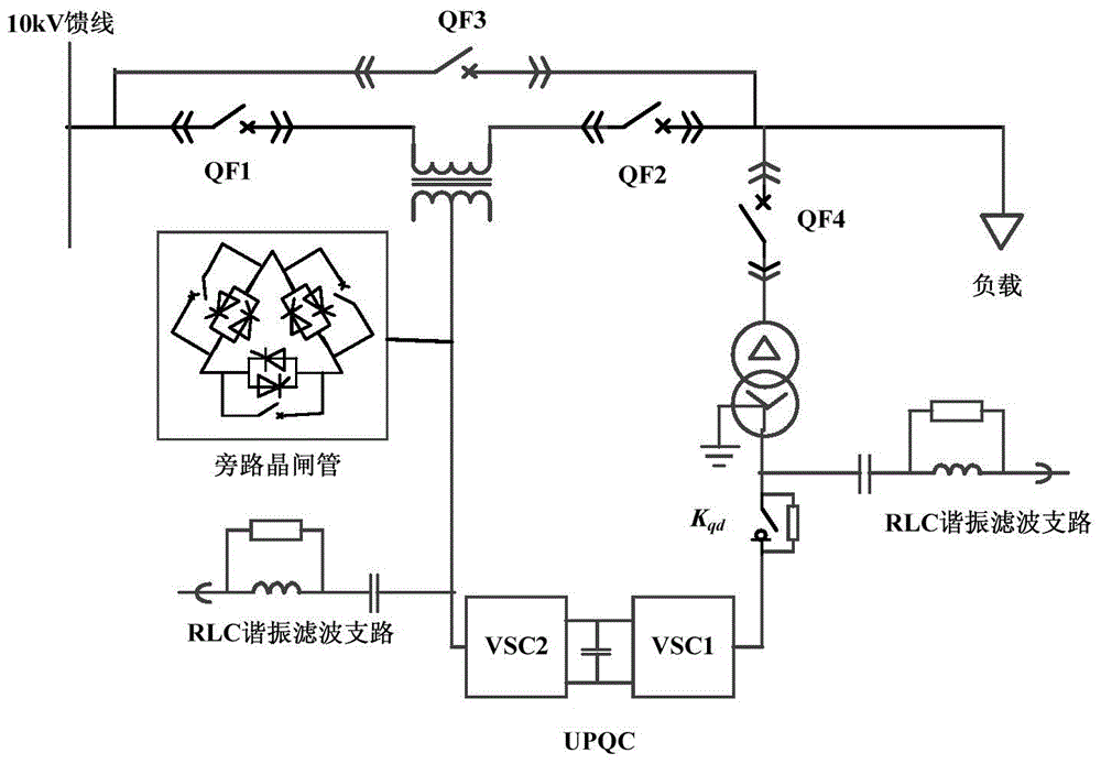
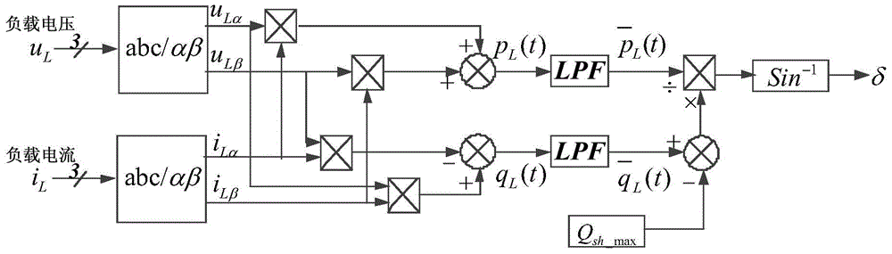
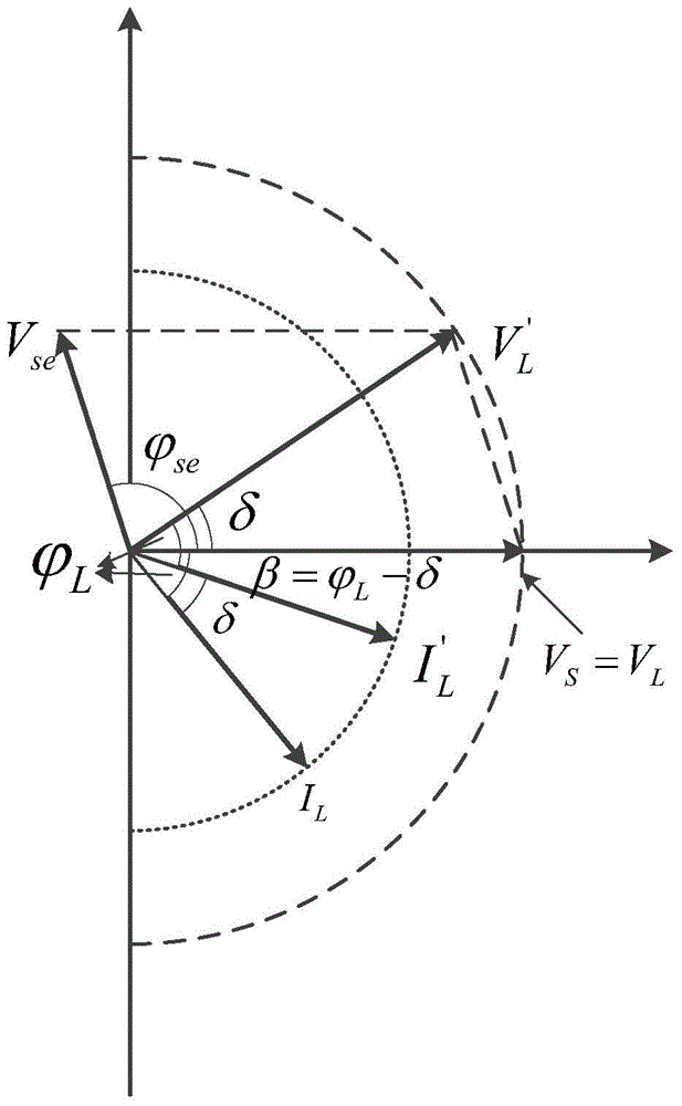
[0043] The present invention specifically relates to a control method for reactive power compensation at the UPQC series side based on the rotation vector method. First, calculate the difference between the instantaneous reactive power required to be compensated by the load in the UPQC access system and the maximum limit value of reactive power compensation at the UPQC parallel side. When the difference is positive, the UPQC series side can start the compensation reactive power algorithm; after the UPQC series side is put into reactive power compensation, it will output a compensation voltage with a specific amplitude and phase. After the action of this voltage, the load voltage will Rotate a certain angle while keeping the load voltage amplitude constant. Therefore, the working state of the load will not change after the compensation is put into the series s...


PUM


Abstract

The invention provides a UPQC series side reactive compensation control method based on a rotating vector method. The method includes the following steps that whether reactive compensation needs to be started for a UPQC series side or not is judged; the voltage amplitude and the phase which need to be output in the UPQC series side reactive compensation process are calculated; the modulating voltage output by an inverter on the UPQC series side is calculated. By the adoption of the UPQC series side reactive compensation control method based on the rotating vector method, when no compensation for the system voltage sag exists in the UPQC series side, a parallel side and the series side jointly conduct compensation on load reactive power, the whole operating range in the UPQC reactive compensation process is widened, and the method has the advantages that control objectives are definite, the response speed is high, and the control effect is good. The method can be applied to increasing UPQC reactive compensation capacity through capacity compensation reactive power in the idle process of the UPQC series side and compensating for the reactive power through idle capacity of other series FACTS devices, and the economical efficiency of power electronic equipment is comprehensively improved.

Description

technical field [0001] The invention relates to a control method, in particular to a control method for UPQC series side reactive power compensation based on a rotation vector method. Background technique [0002] Unified Power Quality Conditioner (Unified Power Quality Conditioner, UPQC), with its excellent working characteristics, can comprehensively solve power quality problems such as voltage fluctuation and flicker, three-phase current imbalance, voltage swell / drop, and voltage and current harmonics through control , and at the same time, the device can also compensate the reactive power required by the load, improve the power factor of the load power supply, and has broad application prospects. [0003] The harm and loss caused by system voltage sag faults are very serious for sensitive users, such as semiconductor manufacturing enterprises, a voltage sag of tens of milliseconds may cause equipment damage, production line shutdown, and huge economic losses. Therefore,...

Claims


Application Information

Patent Timeline
Patent Type & Authority Applications(China)
IPC IPC(8): H02J3/18
CPCH02J3/1807H02J3/1821Y02E40/30
Inventor 田鑫段耀强赵波刘颖英潘爱强
Owner STATE GRID CORP OF CHINA
Why Eureka
Try Eureka