Pipeline inner wall laser cleaning device based on side wall projection

A laser cleaning and pipeline technology, applied in the direction of cleaning hollow objects, cleaning methods and utensils, chemical instruments and methods, etc., can solve problems such as difficult application, achieve simple data segmentation, overcome uneven distribution of pollutants, and improve cleaning efficiency. Effect

Active Publication Date: 2021-12-17
SHENZHEN TECH UNIV
View PDF9 Cites 1 Cited by
  • Summary
  • Abstract
  • Description
  • Claims
  • Application Information

AI Technical Summary

Problems solved by technology

[0004] Aiming at the deficiencies of the existing laser cleaning technology, the present invention provides a laser cleaning device for the inner wall of the pipeline based on side wall projection; it adopts a novel laser cleaning technology for the inner surface of the pipeline based on the front focusing galvanometer system, and skillfully transforms the three-dimensional curved surface The processing is decomposed into two-dimensional scanning, which solves the problem of how to decompose and process complex curved surfaces. The external platform drives the longitudinal movement of the laser scanning head, which can realize layer-by-layer circular scanning along the depth of the pipeline. This technology completely abandons the traditional three-dimensional processing. The idea is to simplify the entire processing process. In addition, through the projection of the high-pulse energy circular spot on the side wall of the pipe, an elliptical spot along the axial direction can be obtained, which can further improve the processing efficiency. There is no need for a processing head or the automatic processing of the pipe during the entire processing process. It solves the bottleneck problem that the traditional laser cleaning technology is difficult to apply to the cleaning of the inner surface of the pipeline

Method used


Image

  • Pipeline inner wall laser cleaning device based on side wall projection
  • Pipeline inner wall laser cleaning device based on side wall projection
  • Pipeline inner wall laser cleaning device based on side wall projection

Examples


Embodiment Construction

[0025] In order to make the purpose, technical solutions and advantages of the embodiments of the present invention clearer, the technical solutions in the embodiments of the present invention will be clearly and completely described below in conjunction with the drawings in the embodiments of the present invention. Obviously, the described embodiments It is a part of the embodiments of the present invention, rather than all embodiments; the components of the embodiments of the present invention described and shown in the accompanying drawings generally can be arranged and designed in various configurations; below in conjunction with the accompanying drawings and specific Embodiments further describe the present invention in detail.

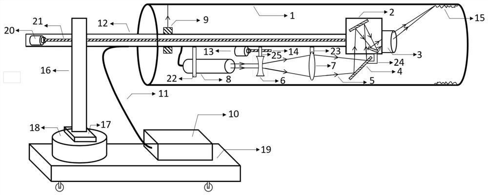
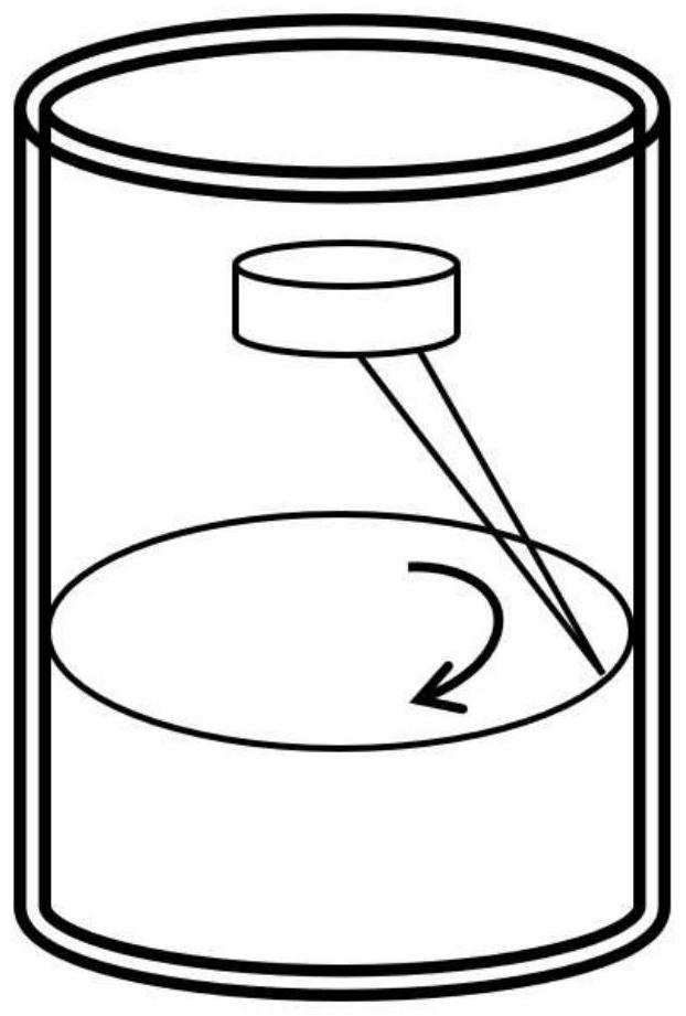
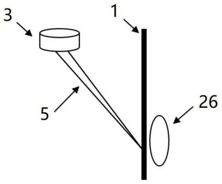
[0026] Such as Figure 1-3 As shown, the present invention provides a laser cleaning device for the inner wall of a pipeline based on side wall projection, which includes a motion control unit and a laser transmission scanning unit.

[0027] The...


PUM


Abstract

The invention provides a pipeline inner wall laser cleaning device based on side wall projection. The pipeline inner wall laser cleaning device comprises a motion control unit and a laser transmission scanning unit. The motion control unit comprises a movable main unit platform, an automatic rotating shaft, a horizontal moving platform, a height adjusting unit, an electric horizontal supporting rod, a first servo motor, a first ball screw and a rotatable laser range finder. The laser transmission scanning unit comprises an optical fiber laser, a transmission optical fiber, a laser head, a support, a concave lens, a convex lens, a second servo motor, a second ball screw, a screw slider, a lens bracket, a reflector, a reflector bracket, a scanning galvanometer and a field lens. After being emitted, a laser beam propagating in the axial direction of a pipeline passes through the concave lens, the convex lens and the reflector and then enters the scanning galvanometer, and through the scanning galvanometer, the laser passes through the field lens and then is focused on dirt on the inner wall of the pipeline. According to the pipeline inner wall laser cleaning device, a machining head or the pipeline does not need to spin in the whole machining process, and the bottleneck problem that a traditional laser cleaning technology is difficult to apply to cleaning of the inner surface of the pipeline is solved.

Description

technical field [0001] The invention belongs to the technical field of laser processing, and in particular relates to a pipeline inner wall laser cleaning device for removing coatings, dirt, oxide layers and other harmful substances on the inner wall of pipelines based on side wall projection. Background technique [0002] Pipeline inner surface cleaning technology is widely used in today's life or industrial production equipment maintenance and other fields. For example, the cleaning of the inner surface of urban water supply and heating equipment pipelines, as well as the cleaning of modern industrial oil pipelines and chemical reaction pipelines, even the cleaning of adhesive residues in the inner bore of gun barrels, the cleaning of radiation in nuclear reaction circulation pipelines, etc. Due to its advantages of high cleaning quality, no consumables, high efficiency and no polluting waste water, laser technology has gradually replaced traditional pipeline inner wall cl...

Claims


Application Information

Patent Timeline
Patent Type & Authority Applications(China)
IPC IPC(8): B08B7/00B08B9/047
CPCB08B7/0042B08B9/047
Inventor 杨焕曹宇郑秀宏何承志王萌李春波杨灿伍叶全
Owner SHENZHEN TECH UNIV
Why Eureka
Try Eureka