
Control device for magnetic suspension bearing system

A magnetic suspension bearing and control device technology, applied in the control field, can solve the problems of magnetic suspension bearing system damage, potential safety hazards, system damage, etc., and achieve the effect of avoiding further damage

Inactive Publication Date: 2015-03-25
ZHUHAI GREE REFRIGERATION TECH CENT OF ENERGY SAVING & ENVIRONMENTAL PROTECTION
View PDF5 Cites 10 Cited by
  • Summary
  • Abstract
  • Description
  • Claims
  • Application Information

AI Technical Summary

Problems solved by technology

However, from the perspective of reliability, this method has great potential safety hazards. The inventor found that when the magnetic suspension bearing system fails, if the magnetic suspension bearing system is first controlled to stop the shaft suspension, and then the motor is controlled to stop the rotation, it is easy to make the The shaft is frictionally rotated under the drive of the motor, which will cause damage to the system. Further, because when the bearing controller fails, the motor controller cannot be notified in real time due to communication delay, which will also cause damage to the system.
[0004] Aiming at the problem that the magnetic suspension bearing system in the prior art is likely to cause further damage when it fails, no effective solution has been proposed so far

Method used


Image

  • Control device for magnetic suspension bearing system
  • Control device for magnetic suspension bearing system
  • Control device for magnetic suspension bearing system

Examples


Embodiment Construction

[0019] It should be noted that, in the case of no conflict, the embodiments in the present application and the features in the embodiments can be combined with each other. The present invention will be described in detail below with reference to the accompanying drawings and examples.

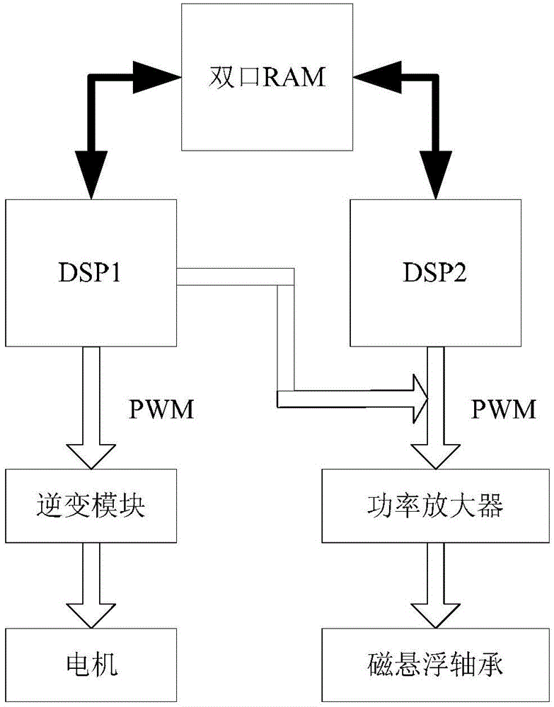
[0020] figure 2 is a schematic structural diagram of a control device for a magnetic suspension bearing system according to an embodiment of the present invention.

[0021] like figure 2 As shown, the magnetic suspension bearing system control device includes a magnetic suspension bearing controller 10 and a motor controller 20, and the magnetic suspension bearing controller 10 is used to control the bearings in the magnetic suspension bearing system. The bearing is a magnetic suspension bearing, and the magnetic suspension bearing controller 10 is mainly used to execute the main control algorithm of the magnetic suspension bearing, so as to control the magnetic suspension bearing to realiz...


PUM


Abstract

The invention discloses a control device for a magnetic suspension bearing system. The control device for the magnetic suspension bearing system comprises a magnetic suspension bearing controller used for controlling a bearing in the magnetic suspension bearing system, and a motor controller used for controlling a motor in the magnetic suspension bearing system, wherein the motor controller is further used for controlling the motor for stopping rotation when the magnetic suspension bearing system is in fault, and the magnetic suspension bearing controller is further used for controlling stopping shaft suspension of the magnetic suspension bearing system after the motor is controlled by the motor controller for stopping rotation. Through the control device, the magnetic suspension bearing system in fault is prevented from being further damaged.

Description

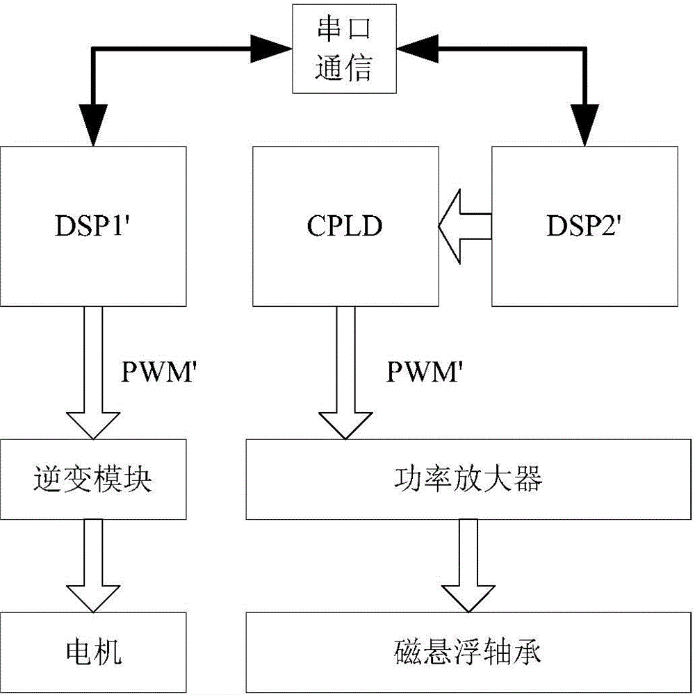
technical field [0001] The invention relates to the field of control, in particular to a control device for a magnetic suspension bearing system. Background technique [0002] The magnetic suspension bearing technology has the advantages of no oil, no friction and low loss. In the magnetic suspension bearing system, the control of the magnetic suspension bearing and the motor control are inseparable. Only when the motor is driven by the shaft can the shaft rotate without friction. [0003] The magnetic suspension bearing system includes the magnetic suspension bearing controller and the motor controller. Since the magnetic suspension bearing controller and the motor controller have great differences in the controller principle and hardware structure, in the prior art, when designing the magnetic suspension bearing system, the The two controllers are designed separately, and the general block diagram is as attached figure 1 shown. figure 1 Among them, DSP1' is the motor con...

Claims


Application Information

Patent Timeline
IPC IPC(8): H02N15/00F16C32/04
Inventor 黄辉胡余生陈东锁胡叨福郭伟林贺永玲
Owner ZHUHAI GREE REFRIGERATION TECH CENT OF ENERGY SAVING & ENVIRONMENTAL PROTECTION
Learn More