False sticking equipment

A technology of equipment and false stickers, which is applied in the direction of electrical components, laminated printed circuit boards, printed circuit manufacturing, etc., can solve problems such as low production efficiency

Inactive Publication Date: 2015-03-25
SUZHOU MIDAS PRECISION ELECTRONICS
View PDF6 Cites 4 Cited by
  • Summary
  • Abstract
  • Description
  • Claims
  • Application Information

AI Technical Summary

Problems solved by technology

[0003] The technical problem to be solved by the present invention is: the production efficiency is not high when the existing artificial fake reinforcement sheet

Method used


Image

  • False sticking equipment
  • False sticking equipment

Examples


Embodiment Construction

[0010] The specific implementation manners of the present invention will be further described in detail below in conjunction with the accompanying drawings and embodiments. The following examples are used to illustrate the present invention, but are not intended to limit the scope of the present invention.

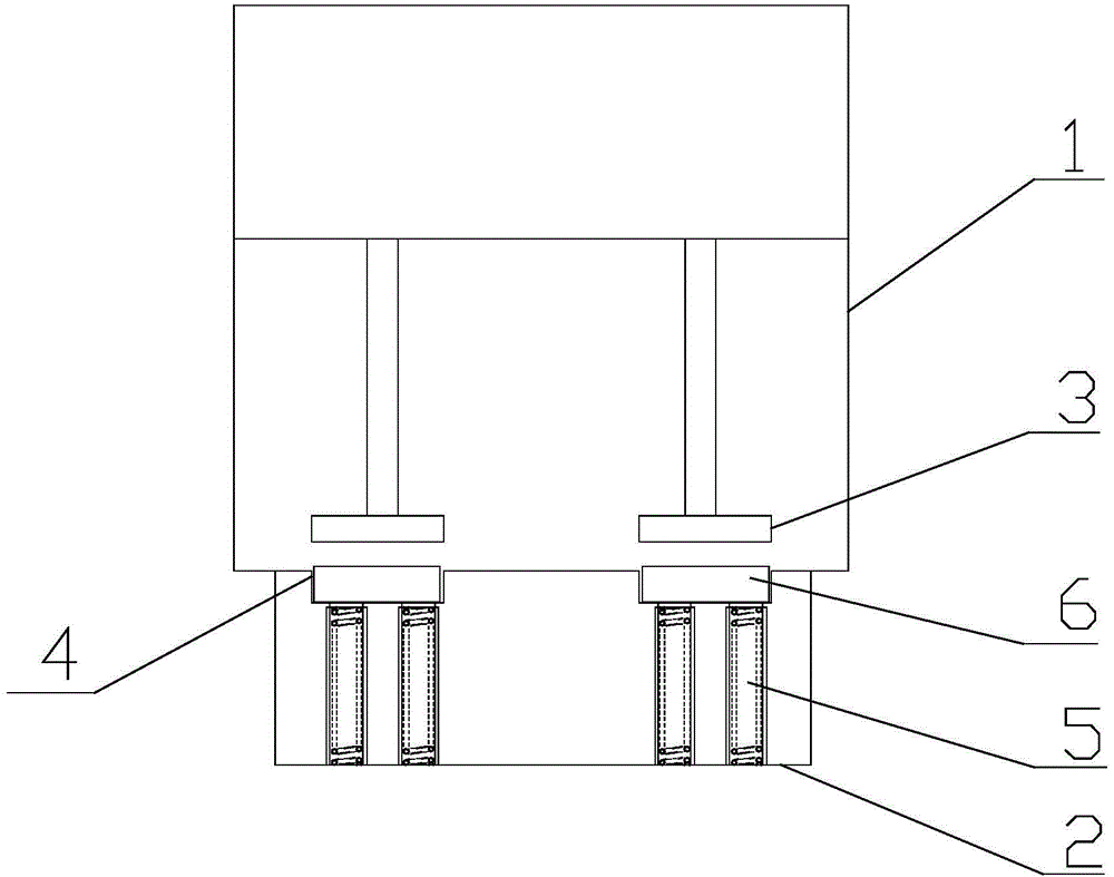
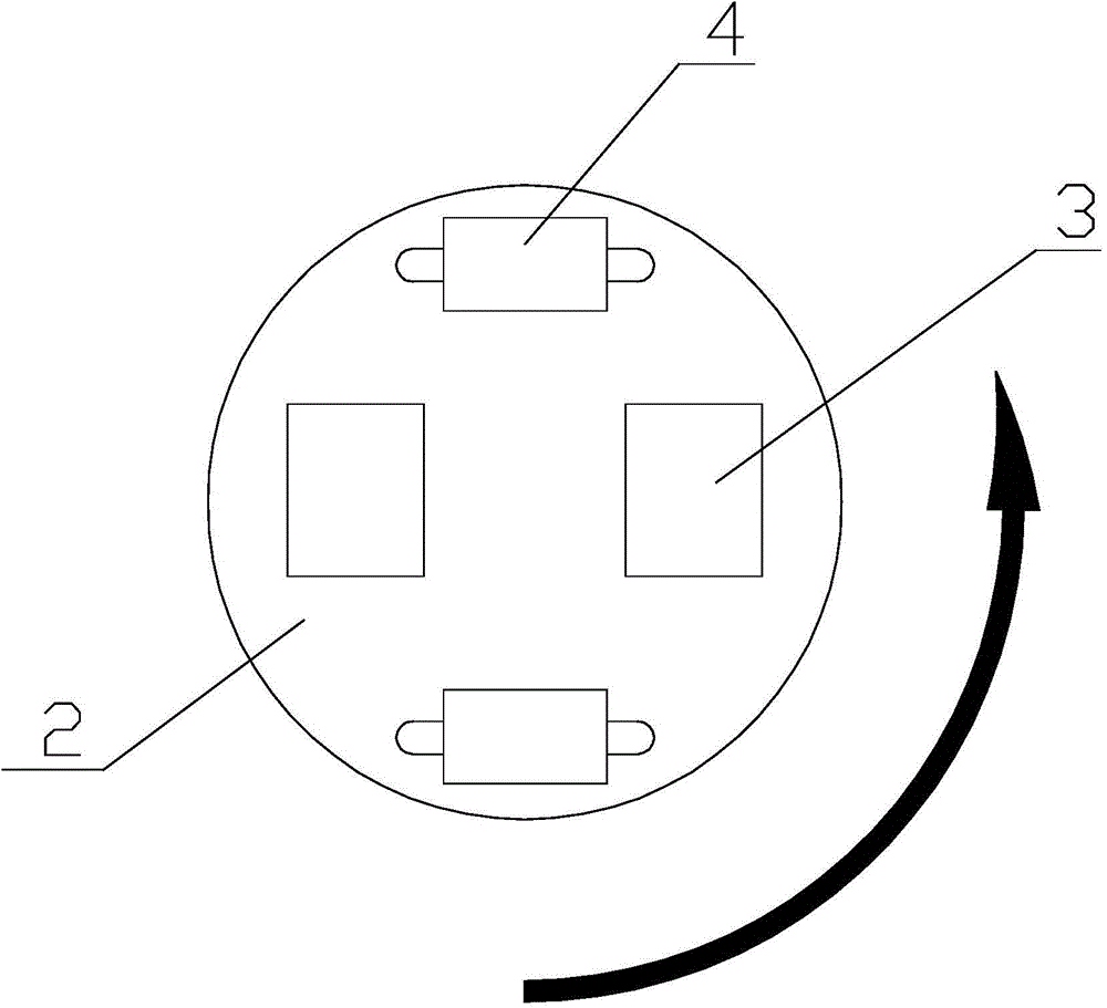
[0011] Such as figure 1 with figure 2 The false pasting equipment shown includes: a rotating table 1 and a base 2 . The rotary table 1 is provided with a hot pressing block 3 . The base 2 is provided with a hot-pressing groove 4, and the bottom of the hot-pressing groove 4 is provided with a spring thimble 5. The functions of the spring thimble 5 are: 1. to keep the reinforcement sheet and the heat-pressed block tightly when they are attached; 2. to prevent the reinforcement sheet from being damaged. Overstressed. The turntable 1 can rotate, rise and fall, and align the hot-press block 3 with the hot-press groove 4 .

[0012] In order to fit the reinforcement sheets ...


PUM


Abstract

The invention discloses false sticking equipment, and relates to the technical field of flexible circuit board processing. The false sticking equipment comprises a rotary table and a base, hot-pressing blocks are arranged on the rotary table, hot-pressing grooves are formed in the base, and spring ejector pins are arranged at the bottoms of the hot-pressing grooves. The rotary table can rotate, ascend and descend, and the hot-pressing blocks are made to be aligned with the hot-pressing grooves.

Description

technical field [0001] The invention relates to the technical field of flexible circuit board processing, in particular to a false pasting device. Background technique [0002] The false pasting process is often used in the production of reinforcement sheets, that is, the thermosetting adhesive is slightly hot-bonded on the reinforcement steel sheet, and then permanently heated and fixed by the customer when using it. At present, the false pasting process mostly adopts manual lamination, which is difficult to improve in terms of improving production efficiency and ensuring production quality. It can effectively reduce costs and reduce the pressure of labor panic in enterprises. It is necessary to provide a device that can automatically realize false pasting. Contents of the invention [0003] The technical problem to be solved by the invention is: the production efficiency is not high when the existing artificial fake reinforcement sheet is applied. [0004] In order to s...

Claims


Application Information

Patent Timeline
Patent Type & Authority Applications(China)
IPC IPC(8): H05K3/00
CPCH05K3/0058H05K2203/1105
Inventor 王中飞
Owner SUZHOU MIDAS PRECISION ELECTRONICS
Why Eureka
Try Eureka