Steel ring machining equipment integrating foot pressing and chamfering

A technology for processing equipment and steel rings, applied in the field of steel ring manufacturing and processing, can solve problems such as low efficiency, production needs to be improved, injuries, etc., and achieve the effects of improving safety and work efficiency, reducing labor intensity of workers, and realizing processing automation.

Active Publication Date: 2021-06-11
NINGBO JINSHIHONG MACHINERY EQUIP CO LTD
View PDF6 Cites 0 Cited by
  • Summary
  • Abstract
  • Description
  • Claims
  • Application Information

AI Technical Summary

Problems solved by technology

[0003] At present, in order to better fit the pot lid, the manufacturing process of the steel ring is relatively complicated. The process usually includes ringing, welding, edge pulling, curling and chamfering. The curling process is completed in a special curling device. After the edge is completed, its shape is as shown in the instruction manual. figure 1 As shown, at this time, the lower end of the steel ring is only bent, and workers need to take it out and put it into a special presser foot device and chamfering device, so that the final product is as shown in the attached manual. figure 2 As shown, but because the steel ring is relatively thin and sharp, the hand is often cut when taking it out, causing injury, and the presser foot and chamfering are divided into two processes, the efficiency is relatively low, and the output needs to be improved

Method used


Image

  • Steel ring machining equipment integrating foot pressing and chamfering
  • Steel ring machining equipment integrating foot pressing and chamfering
  • Steel ring machining equipment integrating foot pressing and chamfering

Examples


Embodiment 1

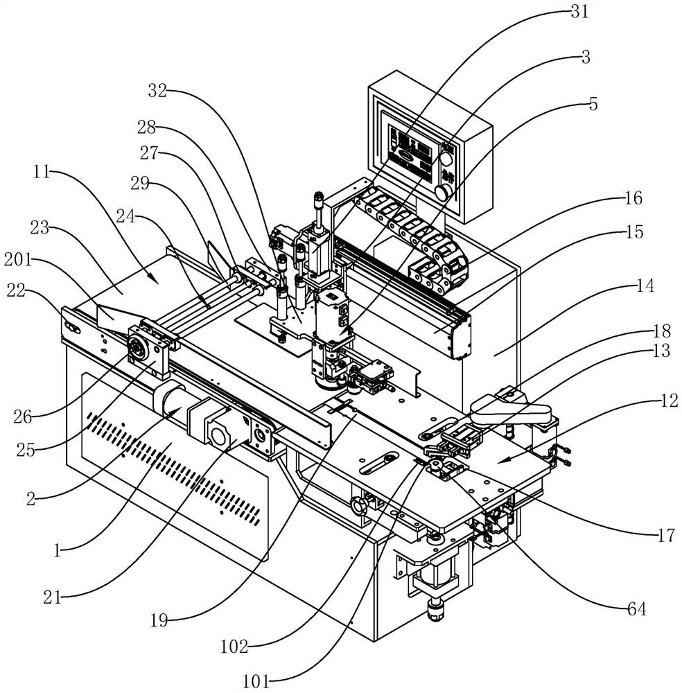
[0035] Embodiment 1: As shown in the figure, a steel ring processing equipment integrating presser foot and chamfering, including

[0036] A frame 1 with a feeding area 11 and a processing area 12 on the frame 1;

[0037] A feeding mechanism 2, the feeding mechanism 2 is arranged at the feeding area 11, and is used to transport the steel rings to be processed to the processing area 12 one by one;

[0038] A mobile frame 3, the mobile frame 3 can move back and forth and be arranged on the frame 1;

[0039] A lifting plate 32, the lifting plate 32 can move up and down and is arranged on the moving frame 3;

[0040] A pressing plate 38, the pressing plate 38 is arranged on the lifting plate 32 by the lifting mechanism, and is used for contacting with the steel ring to be processed;

[0041] An inner chamfering wheel 4, the inner chamfering wheel 4 is rotatably arranged on the lifting plate 32;

[0042] An outer chamfering wheel 42, the outer chamfering wheel 42 can move forwar...

Embodiment 2

[0046] Embodiment 2: As shown in the figure, other structures are the same as Embodiment 1, and the difference is that the feeding mechanism 2 includes a conveying power unit 21, two roller shafts 22 and a belt wound between the two roller shafts 22. Conveyor belt 23, two roller shafts 22 are rotatably arranged on the frame 1 at an interval front and back, and the conveying power unit 21 is arranged on the frame 1, and is used to drive one of the roller shafts 22 to rotate, and the feeding area 11 is also provided with The material guide mechanism 24, the material guide mechanism 24 comprises a first base 25, a first adjustment hand wheel 26, a first two-way screw mandrel 27, a second base 28, two guide shafts 29 and two material guide plates 201, the first A pedestal 25 and a second pedestal 28 are respectively fixed at the feeding area 11 at left and right intervals, and two guide shafts 29 are respectively connected between the first pedestal 25 and the second pedestal 28, a...

Embodiment 3

[0048] Embodiment 3: As shown in the figure, other structures are the same as Embodiment 2. The difference is that a support 36 is fixed at the lower end of the lifting plate 32, and the rotating mechanism 5 includes a rotating motor 51, a rotating rod 52 and a first bearing 53. The first bearing 53 is arranged on the support 36, and the rotating motor 51 is fixed on the lifting plate 32. Presser caster 6 is fixed. In this structure, the rotating motor 51 is fixed on the lifting plate 32, and it moves synchronously with the lifting plate 32. When the rotating motor 51 rotates, it drives the rotating rod 52 to rotate, so that the inner presser caster 6 connected with the rotating rod 52 rotates synchronously. The structure is simple and practical.

[0049] The inner presser caster wheel 6 includes a mutually fixed retaining ring portion 61 and a presser foot portion 62 from top to bottom. The diameter of the retaining ring portion 61 is greater than the diameter of the presser...


PUM


Abstract

The invention discloses steel ring machining equipment integrating foot pressing and chamfering. The steel ring machining equipment comprises a rack, a feeding mechanism, a moving frame, a lifting plate, a pressing plate, an inner chamfering wheel, an outer chamfering wheel, and an inner foot pressing wheel, wherein a feeding area and a machining area are arranged on the rack; the feeding mechanism is arranged at the feeding area; the moving frame can be arranged on the rack in a front-back moving manner; The lifting plate can be arranged on the moving frame in an up-down moving manner; the pressing plate is arranged on the lifting plate through a lifting mechanism and used for making contact with a steel ring to be machined; the inner chamfering wheel is rotatably arranged on the lifting plate; the outer chamfering wheel is arranged on the lifting plate in a front-back moving mode through a displacement mechanism so as to be close to or away from the inner chamfering wheel, and the outer chamfering wheel is matched with the inner chamfering wheel to carry out chamfering action on the upper portion of the steel ring; and the inner foot pressing wheel is rotatably arranged on the lifting plate through a rotating mechanism and is located below the inner chamfering wheel. The equipment has the advantages that automatic machining can be realized, the labor intensity of workers can be reduced, and the safety and the working efficiency can be improved.

Description

technical field [0001] The invention relates to the technical field of steel ring manufacturing and processing, in particular to a steel ring processing equipment integrating a presser foot and chamfering. Background technique [0002] As the market's requirements for cooking pots are getting higher and higher, more and more merchants have introduced glass pot lids. In order to prevent the edges of the pot lids from being scratched and cracked, glass pot lids need to be made of steel rings during the manufacturing process. side. [0003] At present, in order to better fit the pot lid, the manufacturing process of the steel ring is relatively complicated. The process usually includes ringing, welding, edge pulling, curling and chamfering. The curling process is completed in a special curling device. After the edge is completed, its shape is as in the attached figure 1 As shown, at this time, the lower end of the steel ring is only bent, and workers need to take it out and p...

Claims


Application Information

Patent Timeline
Patent Type & Authority Applications(China)
IPC IPC(8): B23P23/04
CPCB23P23/04
Inventor 王贵文
Owner NINGBO JINSHIHONG MACHINERY EQUIP CO LTD
Why Eureka
Try Eureka