Magnetic combined frame

A frame and magnetic technology, applied in the field of magnetic combination frame, can solve the problems of screw hanging, inconvenient installation and disassembly, damage to equipment, etc., and achieve the effect of simple disassembly

Inactive Publication Date: 2015-03-25
TIANJIN JUZHAN MACHINE ROOM EQUIP
View PDF6 Cites 0 Cited by
  • Summary
  • Abstract
  • Description
  • Claims
  • Application Information

AI Technical Summary

Problems solved by technology

There is no way to place many unified cabinets
And now some combined cabinets are fixed with screws, which makes it very inconvenient to install and disassemble.
And the protruding screws could catch on or even damage the device

Method used


Image

  • Magnetic combined frame
  • Magnetic combined frame
  • Magnetic combined frame

Examples


Embodiment Construction

[0014] The present invention will be described in detail below in conjunction with the accompanying drawings.

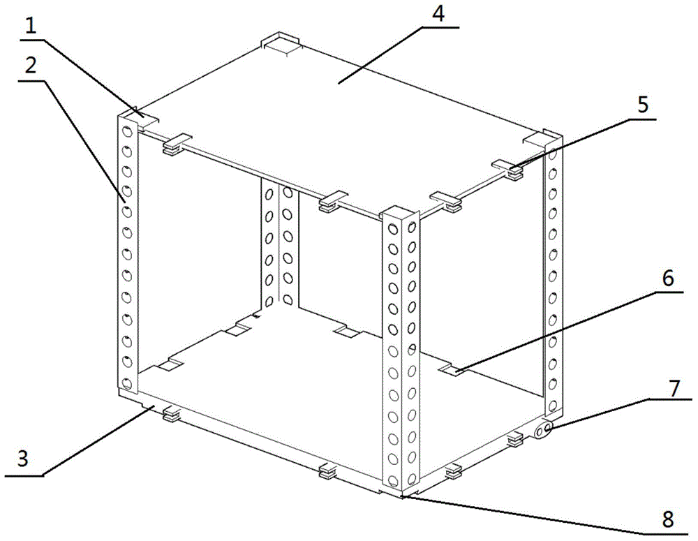
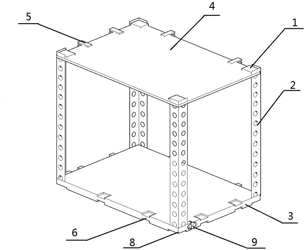
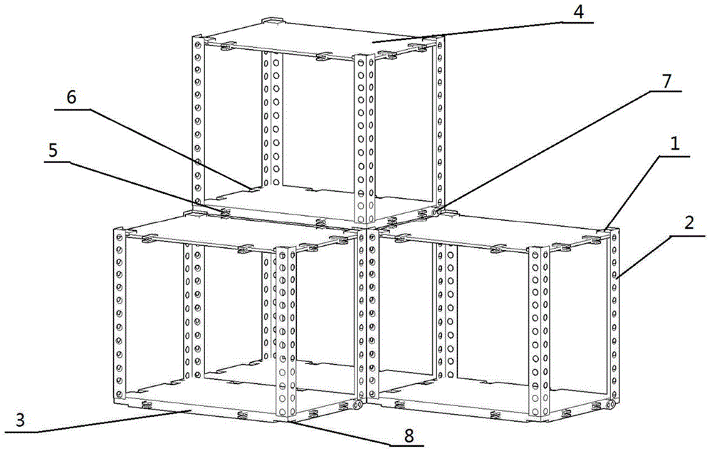
[0015] Such as figure 1 , figure 2 , image 3 As shown, the magnetic composite frame is made up of a supporting angle frame 2, a top plate 4 and a bottom plate 3, and the top plate 4 and the bottom plate 3 are the same rectangular plates; A support angle frame 2; the cross-section of the support angle frame 2 is 'L' type, and fits with the corner of the top plate 4; one end of the support angle frame 2 is connected with the top plate 4, and the other end is connected with the bottom plate 3; Described top plate 4, bottom plate 3 and supporting corner frame 2 constitute a rectangular parallelepiped frame; The one side that is positioned at the outside of rectangular parallelepiped framework on described top plate 4 is provided with some N pole electromagnetic bayonet sockets 1; A number of S pole electromagnetic card slots 8 are arranged on the top and correspond ...


PUM


Abstract

The invention provides a magnetic combined frame. According to the technical scheme, the magnetic combined frame is composed of supporting corner brackets, a top plate and a bottom plate. The top plate and the bottom plate are the same rectangular plates. The four corners of the top plate are provided with the four supporting corner brackets respectively, and the four supporting corner brackets are perpendicular to the surface of the top plate. The cross section of each supporting corner bracket is of an L shape. The supporting corner brackets are attached to the corners of the top plate. One end of each supporting corner bracket is connected with the top plate, and the other end of each supporting corner bracket is connected with the bottom plate. The top plate, the bottom plate and the supporting corner brackets form a cuboid-shaped frame body. A plurality of N-pole electromagnetic bayonets are formed in the top plate and located on the surface of the outer side of the cuboid-shaped frame body. The magnetic combined frame has the advantages that the frame can be combined and assembled in any environment, and space usage is maximized; in the installation process, a user just needs to place all the sides of the magnetic combined frame into corresponding clamping grooves and then power on the magnetic combined frame to activate electromagnets.

Description

technical field [0001] The invention belongs to the field of machine room cabinets, in particular to a magnetic combination frame. Background technique [0002] With the strengthening of Internet popularization in my country, more and more enterprises, schools, shopping malls and supermarkets need to configure a large number of electronic equipment. The centralized control of so many electronic devices needs to be placed and operated in a unified computer room. Too much equipment needs to be placed, and most businesses or organizations don't have much space to put these machines. So there are a lot of computer rooms set up in some special-shaped rooms. These rooms may be higher in one place and lower in another. Many unified cabinets cannot be placed in it. And now some combined cabinets are fixed with screws, which makes it inconvenient to install and disassemble. And the protruding screws can catch on or even damage the device. So now there is an urgent need for a ca...

Claims


Application Information

Patent Timeline
Patent Type & Authority Applications(China)
IPC IPC(8): H05K7/18
Inventor 李元春
Owner TIANJIN JUZHAN MACHINE ROOM EQUIP
Why Eureka
Try Eureka