Engine control valve having improved sealing

A technology for controlling valves and engines, applied to engine components, machines/engines, lift valves, etc., can solve problems such as seal damage

Inactive Publication Date: 2015-03-25
VALEO SYST DE CONTROLE MOTEUR
View PDF5 Cites 0 Cited by
  • Summary
  • Abstract
  • Description
  • Claims
  • Application Information

AI Technical Summary

Problems solved by technology

Therefore, in order to provide a correct seal between the liner and the casting ele

Method used


Image

  • Engine control valve having improved sealing
  • Engine control valve having improved sealing
  • Engine control valve having improved sealing

Examples


Embodiment Construction

[0032] figure 1 has been described. Elements that are common in this and other figures retain the same reference numerals.

[0033] The engine control valve according to the invention may, for example, be an EGR valve, which regulates the flow rate of gases through the circuit connecting the exhaust circuit to the intake circuit of the vehicle's internal combustion engine.

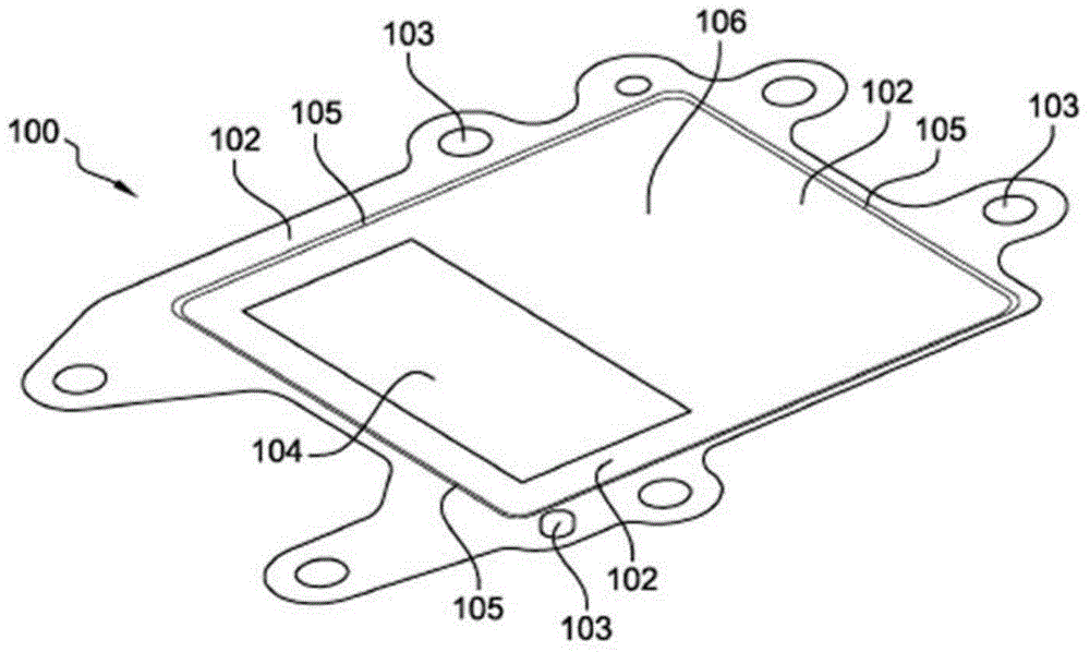
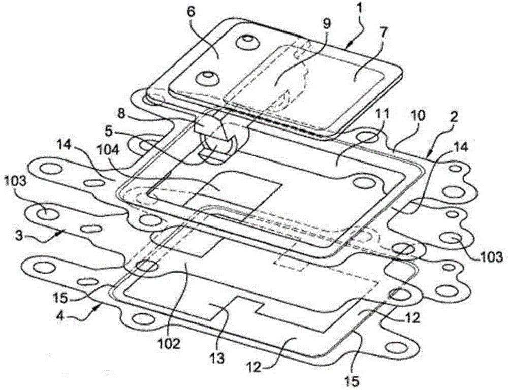
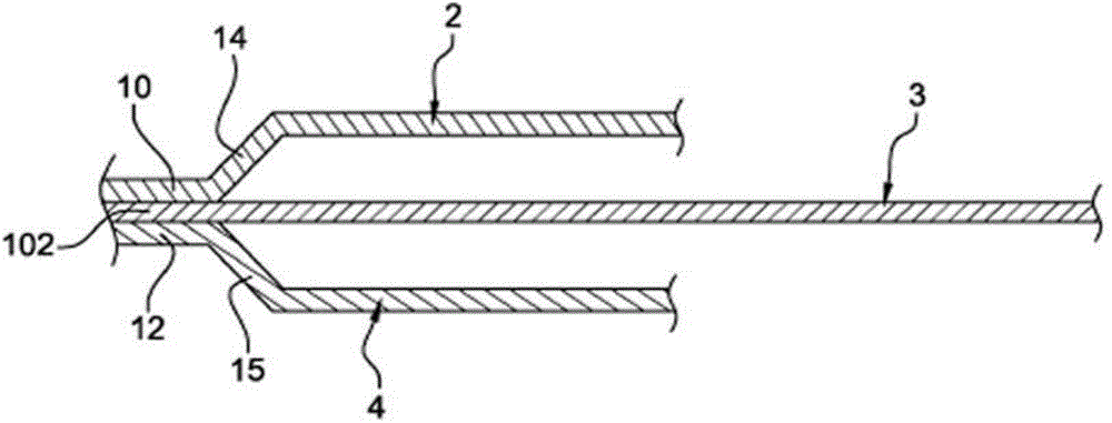
[0034] refer to figure 2 , the engine control valve according to the invention employs a petal 1 and three gaskets 2, 3, 4 intended to be inserted between two cast elements of the body of said valve. The petal 1 comprises a rotating pin 5 and a first part 6 and a second part 6, said parts 6, 7 being arranged on either side of said pin 5, in continuation of each other. The two parts 6, 7 have a small thickness and are rigidly fastened together. The general outline of the petal 1 delimited by these two parts 6 , 7 is substantially rectangular, each of said parts 6 , 7 also having a rectangular shape.

...


PUM


Abstract

The invention relates to an engine control valve which includes a body defining an inner duct and a rotatably mobile shutter (1), said shutter (1) being capable of pivoting between an open position enabling gas to flow into the duct and a closed position sealing the duct, the valve including a first system (2, 4) for sealing the duct relative to the outside of the body and a second sealing system (3), separate from the first, and ensuring that the shutter (1) is sealed when in the closed position thereof.

Description

technical field [0001] The present invention relates to an engine control valve with improved sealing. A valve of this type may, for example, be fitted in the gas supply circuit of a vehicle's internal combustion engine to regulate the flow rate of EGR (exhaust gas recirculation) gases in the circuit, making it possible to suck in a portion of the exhaust gases leaving the engine in order to transfer them in the Reinjection upstream of said engine. The principle of operation of this type of valve is based on the controlled rotation of a flap which is movable from a fully open position (for allowing the passage of gas) to a closed position (for blocking this passage). The subject of the invention is an engine control valve with improved sealing. Background technique [0002] The engine control valve thus has a petal which is pivotally mounted on the rotary pin. The petal may comprise a first portion and a second portion separated by the pin. When the flap is in the closed...

Claims


Application Information

Patent Timeline
IPC IPC(8): F16K1/226F02M25/07F16K11/052
CPCF02M26/00F16K1/2263F16K11/0525F02M26/70
Inventor G.霍德布尔格
Owner VALEO SYST DE CONTROLE MOTEUR
Why Eureka
Try Eureka