Welding back ventilation protection device and welding back ventilation method

A protective device and back-facing technology, which is applied in the field of welding back-to-back ventilation protection devices, and can solve problems such as long ventilation time

Active Publication Date: 2015-04-01
CHINA HANGFA SOUTH IND CO LTD
View PDF8 Cites 2 Cited by
  • Summary
  • Abstract
  • Description
  • Claims
  • Application Information

AI Technical Summary

Problems solved by technology

[0006] The main purpose of the present invention is to provide a welding back ventilation protection device and a weld

Method used


Image

  • Welding back ventilation protection device and welding back ventilation method
  • Welding back ventilation protection device and welding back ventilation method
  • Welding back ventilation protection device and welding back ventilation method

Examples


Embodiment Construction

[0027] It should be noted that, in the case of no conflict, the embodiments in the present application and the features in the embodiments can be combined with each other. The present invention will be described in detail below with reference to the accompanying drawings and examples.

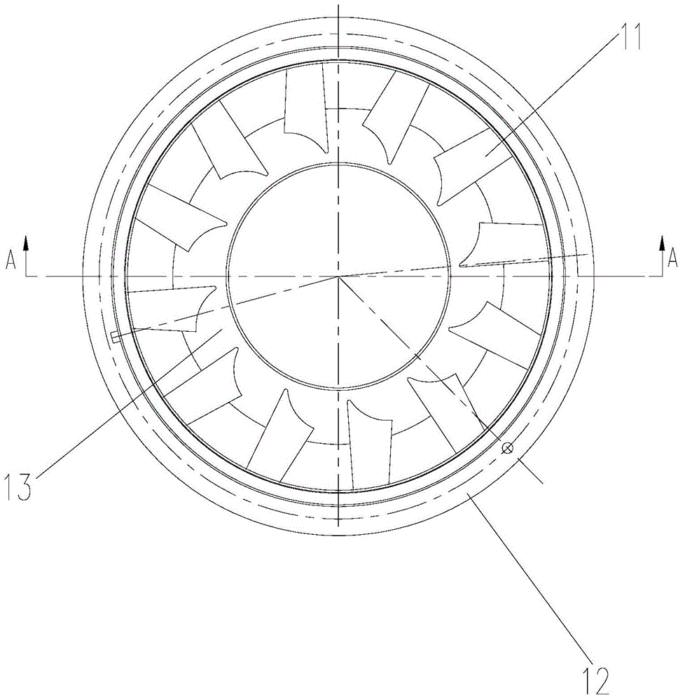
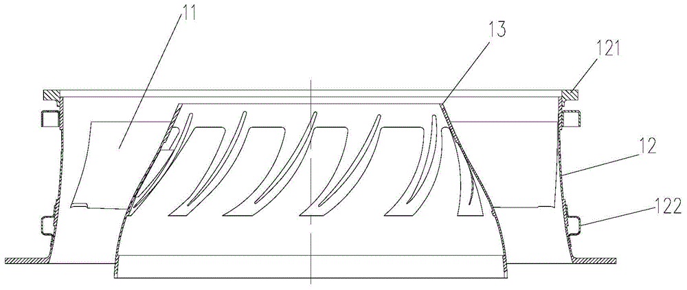
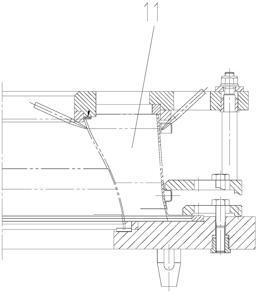
[0028] Such as Figures 4 to 6 As shown, according to the embodiment of the present invention, the welding back ventilation protection device is used for welding the impeller, the impeller includes a wheel body and the blade 11 welded on the wheel body, and the welding back ventilation protection device includes a ventilation seat 20 and two ventilation structures 30. The ventilation seat 20 is provided with an air channel connected to the air source, and the ventilation seat 20 is used to connect the air source and the ventilation structure 30 . Two ventilation structures 30 are fixedly connected to the ventilation seat 20, and the two ventilation structures 30 are arranged at intervals, and...


PUM


Abstract

The invention provides a welding back ventilation protection device and a welding back ventilation method. The welding back ventilation protection device is used for welding an impeller; the impeller comprises a wheel body and a blade welded to the wheel body; the device is characterized by comprising a ventilation seat and two ventilation structures, wherein the ventilation seat is provided with a ventilation passage connected with an air source; the two ventilation structures are fixedly connected to the ventilation seat and are spaced from each other; a welding region for accommodating the blade is arranged between the two ventilation structures; the ventilation structures are provided with at least one air outlet small hole; the air outlet small hole faces towards the welding region. The welding back ventilation protection device ventilates directly, so the ventilation time can be saved.

Description

technical field [0001] The invention relates to the field of blade welding protection, in particular to a welding back ventilation protection device and a welding back ventilation method. Background technique [0002] Figures 1 to 3 Shows the structural diagram of the impeller and the fixture to be welded in the prior art, the wheel body of the impeller to be welded includes an outer ring body 12 and an inner ring body 13 arranged in the outer ring body 12, and the blades 11 are welded on the outer ring body Between the body 12 and the inner ring body 13. The outer ring body 12 is also welded with an outer ring wall ring 122 , and the upper end of the outer ring body 12 is also welded with a mounting ring 121 . The welding sequence is as follows: first, the blade 11 is welded to the outer wall of the inner ring body 13 and the inner wall of the outer ring body 12, then the outer ring wall ring 122 of the outer ring body 12 is positioned and welded from bottom to top, and f...

Claims


Application Information

Patent Timeline
IPC IPC(8): B23K9/32
CPCB23K9/325
Inventor 范雪莉何旺君苏波陈昊袁利娜
Owner CHINA HANGFA SOUTH IND CO LTD
Why Eureka
Try Eureka