Method for compensating motion path of mechanical arm based on vision measurement

A compensation method and motion path technology, applied in manipulators, manufacturing tools, etc., can solve problems such as bruises or scratches on spacecraft products, difficult installation work, and small installation space, so as to achieve safer and more reliable motion, solve assembly problems, High safety effect

Inactive Publication Date: 2015-04-01
BEIJING INST OF SPACECRAFT ENVIRONMENT ENG
View PDF6 Cites 50 Cited by
  • Summary
  • Abstract
  • Description
  • Claims
  • Application Information

AI Technical Summary

Problems solved by technology

This assembly method has certain limitations: for the installation of large-depth parts, due to the limitation of the operator's arm span, it is difficult to complete the installation work; for large-mass parts, manual lifting for a long time is likely to cause fatigue and affect the operation safety; in the case of narrow operating space, it is difficult to adjust the posture of the installed part by manual lifting in a small space, and it is easy to collide with surrounding objects; for parts that require high installation accuracy, manual installation is difficult to control Installation accuracy, long adjustment time
The assembly quality of this type of operation is greatly affected by the operator's person

Method used


Image

  • Method for compensating motion path of mechanical arm based on vision measurement

Examples


Embodiment Construction

[0037] The method for compensating the motion path of the manipulator based on vision measurement of the present invention will be further described below in conjunction with the accompanying drawings. This description is only exemplary and not intended to limit the protection scope of the present invention.

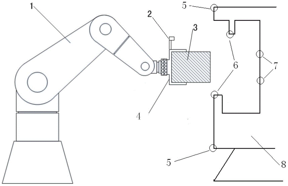
[0038] see figure 1 , figure 1 It shows the operation process of applying the robotic arm based on vision measurement of the present invention to the assembly of spacecraft, wherein the binocular vision sensor 2 is installed on the end effector 4 of the robotic arm 1, and the workpiece 3 to be assembled is clamped by the end effector 4, The target assembly position of the workpiece 3 to be assembled is at the characteristic point 7 of the internal target assembly position of the spacecraft 8 , and the mechanical arm 1 must go deep into the interior of the spacecraft 8 along the way and avoid collision with the protrusion 6 of the spacecraft. The feature points 5 on the ...


PUM


Abstract

The invention discloses a method for compensating a motion path of a mechanical arm based on vision measurement. Vision guides the mechanical arm to move. According to the method, due to vision measurement, the position of the mechanical arm, the position of a spacecraft and a position to be mounted are different from theoretical positions in a theoretical model, and a path planning deviation of the mechanical arm is compensated, so that a control effect on safe get in and get out of a narrow space is achieved, and a requirement on high-precision and high-reliability assembling of the spacecraft is met. Due to the method, an error between an actual position of the spacecraft and the theoretical position of an ideal model is identified, and the motion path of the mechanical arm is compensated, so that the position and the path can be more precisely controlled, and the control effect on safe get in and get out of the narrow space is achieved. The measurement method disclosed by the invention is wide in application range and can be applied to a spacecraft assembling process for different types under different assembling working conditions.

Description

technical field [0001] The invention belongs to the technical field of manipulator control, and in particular relates to a method for compensating the motion path of a manipulator by using visual measurement. Background technique [0002] The development of spacecraft has the characteristics of single piece and small batch. The current assembly operation relies heavily on manual operations, supplemented by simple tools such as spreaders, elevators, and ladders to assemble different spacecraft. This assembly method has certain limitations: for the installation of large-depth parts, due to the limitation of the operator's arm span, it is difficult to complete the installation work; for large-mass parts, manual lifting for a long time is likely to cause fatigue and affect the operation safety; in the case of narrow operating space, it is difficult to adjust the posture of the installed parts by manual lifting in a small space, and it is easy to collide with surrounding objects;...

Claims


Application Information

Patent Timeline
IPC IPC(8): B25J13/08B25J19/04
Inventor 易旺民卫月娥刘宏阳唐赖颖姜旭胡瑞钦傅浩张立建张成立于兆吉
Owner BEIJING INST OF SPACECRAFT ENVIRONMENT ENG
Why Eureka
Try Eureka